Microminiature power converter

a power converter and micro-miniature technology, applied in the direction of process and machine control, instruments, and the details of the semiconductor/solid-state device, can solve the problems of reducing the mounting area of the power module, affecting the miniaturization of electronic equipment, and affecting the conversion efficiency of dc-dc converters

Active Publication Date: 2005-08-16
FUJI ELECTRIC CO LTD
View PDF7 Cites 89 Cited by
  • Summary
  • Abstract
  • Description
  • Claims
  • Application Information

AI Technical Summary

Problems solved by technology

That is, the conversion efficiency of the DC-DC converter becomes low.
However, since individual parts are arranged and mounted on the same substrate, the reduction in mounting area of the power module is restricted.
Especially, a magnetic induction part such as an inductor or a transformer has a very large volume as compared with an integrated circuit, it is the most serious restriction in the miniaturization of the electronic equipment.
However, there were still problems that the number of individual chip parts is large, and the mounting area is large.
Besides, since the DC resistance is increased, power loss is also increased.

Method used


Image

  • Microminiature power converter
  • Microminiature power converter
  • Microminiature power converter

Examples


first embodiment

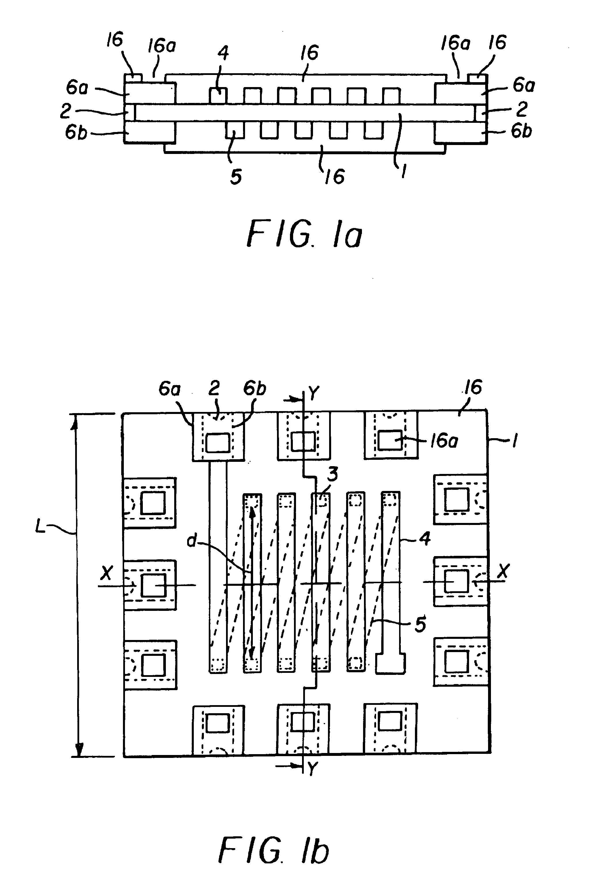
[0018]FIG. 1(a) is a sectional structural view of a microminiature power converter of the invention;

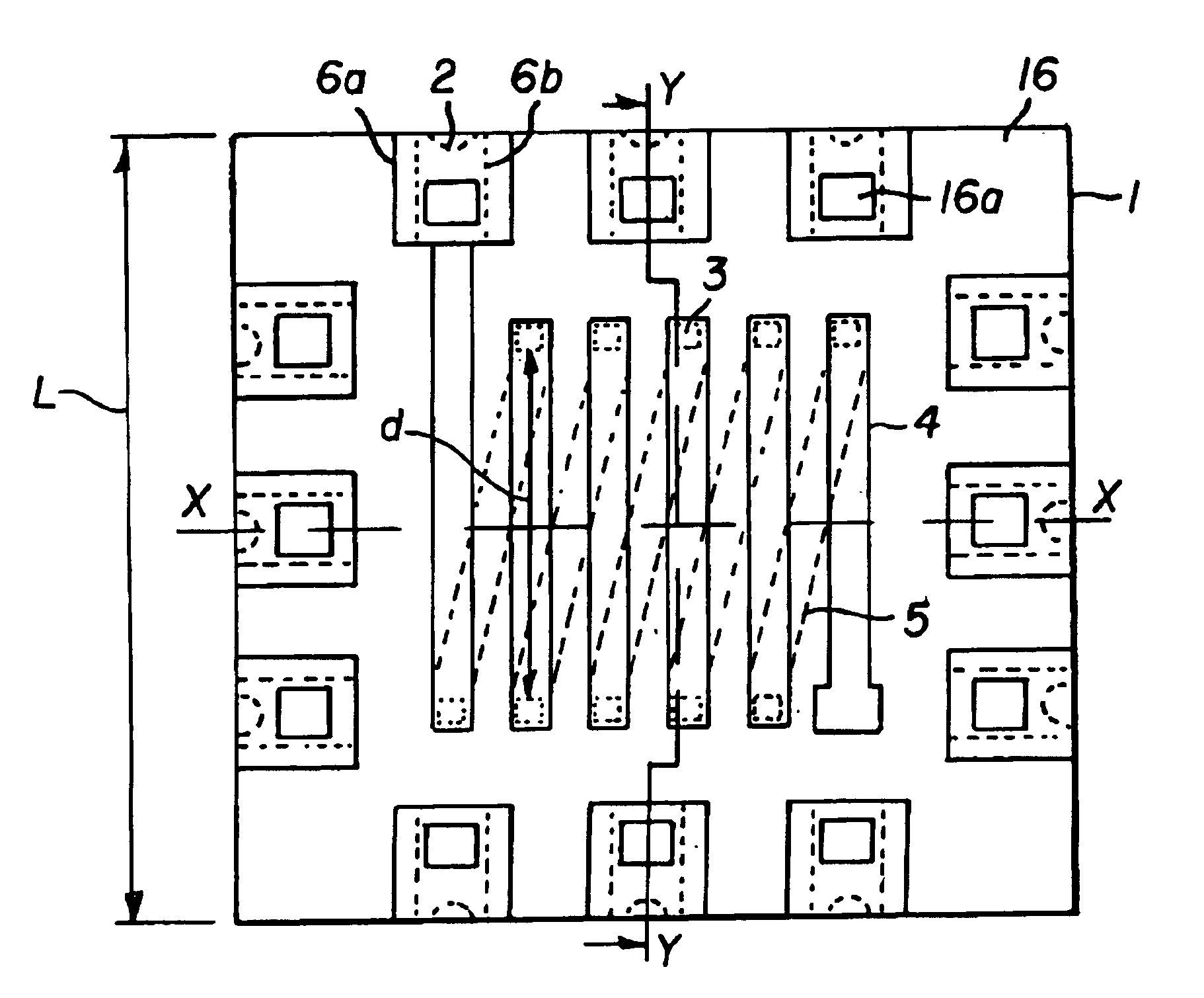
[0019]FIG. 1(b) is a plan view of the microminiature power converter illustrated in FIG. 1(a);

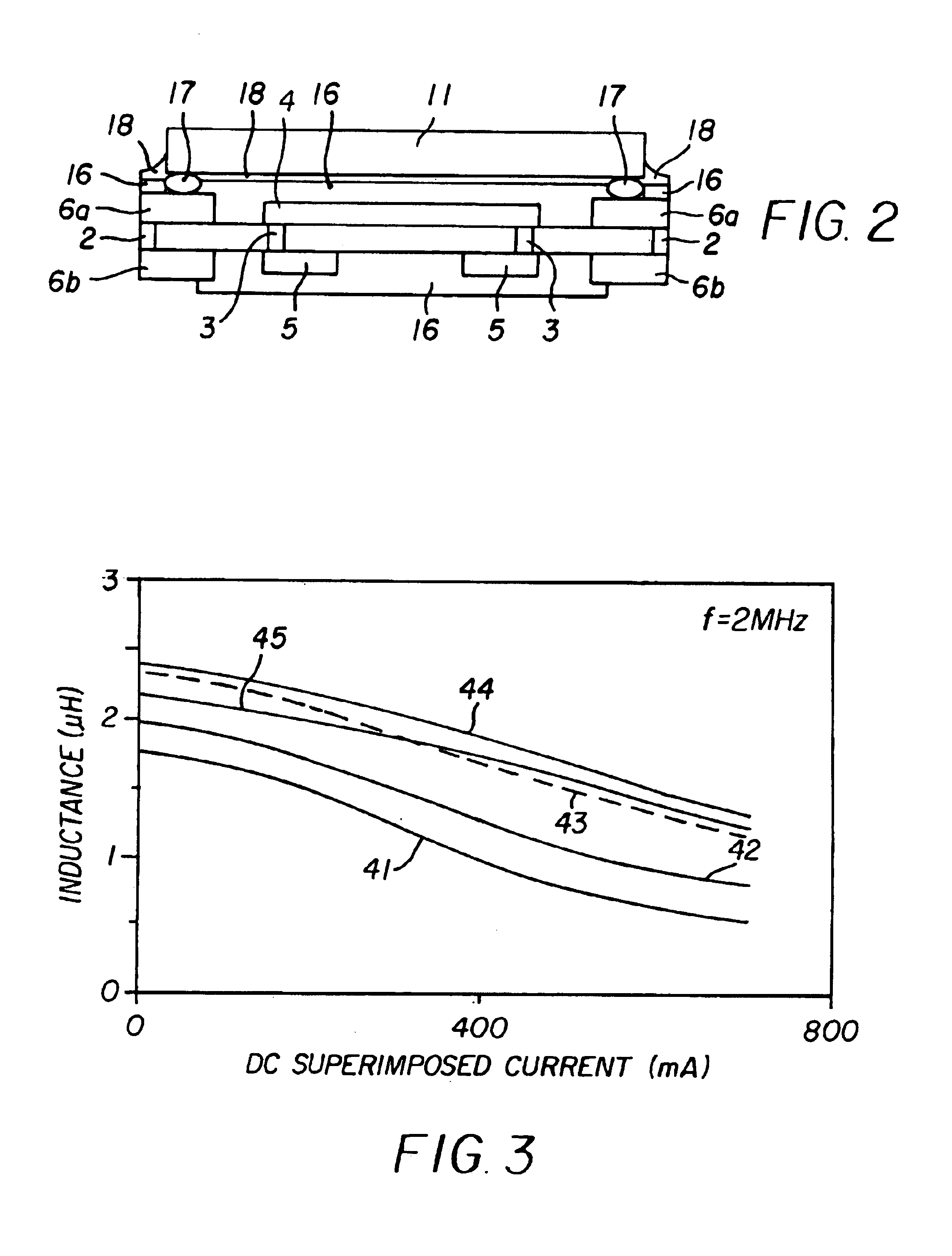
[0020]FIG. 2 is a main part sectional view of the microminiature power converter;

[0021]FIG. 3 illustrates a superposition characteristic of the inductor of FIG. 1(a).

[0022]FIGS. 4(a)-4(h) illustrate a fabrication method of the inductor of FIG. 1(a), in which FIGS. 4(a) to 4(h) are main part process sectional views shown in process sequence;

second embodiment

[0023]FIG. 5 is a main part sectional view of a microminiature power converter of the invention;

[0024]FIG. 6 illustrates a DC superposition characteristic of an inductor illustrated in the converter of FIG. 5;

third embodiment

[0025]FIG. 7(a) illustrates a microminiature power converter of the invention in plan view;

[0026]FIG. 7(b) is a main part sectional view taken along line X—X of FIG. 7(a).


PUM

PropertyMeasurementUnit
thicknessaaaaaaaaaa
thicknessaaaaaaaaaa
frequencyaaaaaaaaaa

Abstract

A microminiature power converter includes a semiconductor substrate on which a semiconductor integrated circuit is formed, a thin film magnetic induction element, and a capacitor. The thin film magnetic induction element includes a magnetic insulating substrate, and a solenoid coil conductor in which a first conductor is formed on a first principal plane of the magnetic insulating substrate, a second conductor is formed on a second principal plane of the magnetic insulating substrate, and a connection conductor is formed in a through hole passing through the magnetic insulating substrate are connected. A relationship of a length L of the magnetic insulating substrate in a direction vertical to a magnetic field generated by the solenoid coil and a length d of the coil conductor is d≧L / 2.

Description

DETAILED DESCRIPTION OF THE INVENTION[0001]The present invention relates to a microminiature power converter, such as a DC-DC converter, constituted by a semiconductor integrated circuit (hereinafter referred to as an IC) formed on a semiconductor substrate and a passive component such as a coil, a capacitor and a resistor.[0002]In recent years, electronic information equipment, especially various portable types of electronic information equipment, have become remarkably widespread. Most types of the electronic information equipment have batteries as power sources and include built-in power converters such as DC-DC converters. In general, the power converter is constructed as a hybrid module in which individual parts of active components, such as switching elements, rectifiers and control ICs, and passive elements, such as coils, transformers, capacitors and resistors, are located on a ceramic board or a printed board of plastic or similar material.[0003]FIG. 13, for example, is a c...

Claims


Application Information

Patent Timeline
Patent Type & Authority Patents(United States)
IPC IPC(8): H01F17/00H01L27/01H02M7/00H01F27/28H01F27/255H01F27/32H01F30/00H01L23/12H02M3/155
CPCH01F17/0033H01L27/016H02M7/003H01L2224/73204H01L2924/13091H01L2924/00
Inventor EDO, MASAHARUHAYASHI, ZENCHI
Owner FUJI ELECTRIC CO LTD
Why Eureka
Try Eureka