Micro-flexure suspension including piezoelectric elements for secondary actuation

Inactive Publication Date: 2005-08-16
MAXTOR
View PDF13 Cites 44 Cited by
  • Summary
  • Abstract
  • Description
  • Claims
  • Application Information

AI Technical Summary

Benefits of technology

[0011]Therefore, one advantage of the present invention is that the mass and size of the elements which are moved in secondary actuation is reduced, thereby improving dynamics and reducing windage excitation.
[0012]Another advantage of the present invention is that since the micro-flexure suspension is a separate element which is attached directly to a flexure of standard design, there is no requirement to alter many of the basic design or manufacturing processes for making the flexure or load beam. Accordingly, the micro-flexure suspension of the present invention can be incorporated within current actuator designs minimizing new efforts in design and manufacturing.
[0013]Yet another advantage of the present invention is that although precise secondary actuation control is provided, this is not achieved with any sacrifice in the flight characteristics of the slider and flexure because the micro-actuator has a reinforced construction to inhibit undesirable vertical/perpendicular movement of the flexure with respect to the micro-flexure thereby maintaining gimballing stiffness of the flexure.
[0014]The present invention provides a micro-flexure which attaches directly to a standard flexure, and the slider directly attaches to the micro-flexure. Coarse positioning of the actuator is achieved in the conventional manner as by a voice coil motor. Secondary actuation is achieved by movement of the slider on the micro-flexure by use of piezoelectric elements which are capable of imparting movement on the micro-flexure in relatively small but precise displacements. The micro-flexure is designed such that movement imparted to the slider is achieved in a plane parallel to the plane of the magnetic storage disk surface, and out of plane movements are minimized by a pair of reinforcing legs which provide the stiffness to resist such out of plane movements.
[0015]More specifically, the micro-flexure includes a base section and a tongue section extending from the base section, both sections being offset from the standard flexure to prevent contact between the sections and the standard flexure. The base and tongue sections may be collectively referred to as a slider carrying section because the base and tongue sections are integrally formed, and the slider is attached to and supported by both the

Problems solved by technology

Because of the trend in recent years to provide greater storage capacity on a storage disk, track widths have become increasingly narrower which makes it more difficult for the read/write heads to accurately read and write information to and from the magnetic disks.
The actuator has limited ability to accurately position a slider across the data tracks.
While the above inventions may be adequate for their intended purposes, one particular drawback to previous micro/milli-actuator designs is that the secondary actuator mechanism actuates not only the slider, but al

Method used


Image

  • Micro-flexure suspension including piezoelectric elements for secondary actuation
  • Micro-flexure suspension including piezoelectric elements for secondary actuation
  • Micro-flexure suspension including piezoelectric elements for secondary actuation

Examples


Embodiment Construction

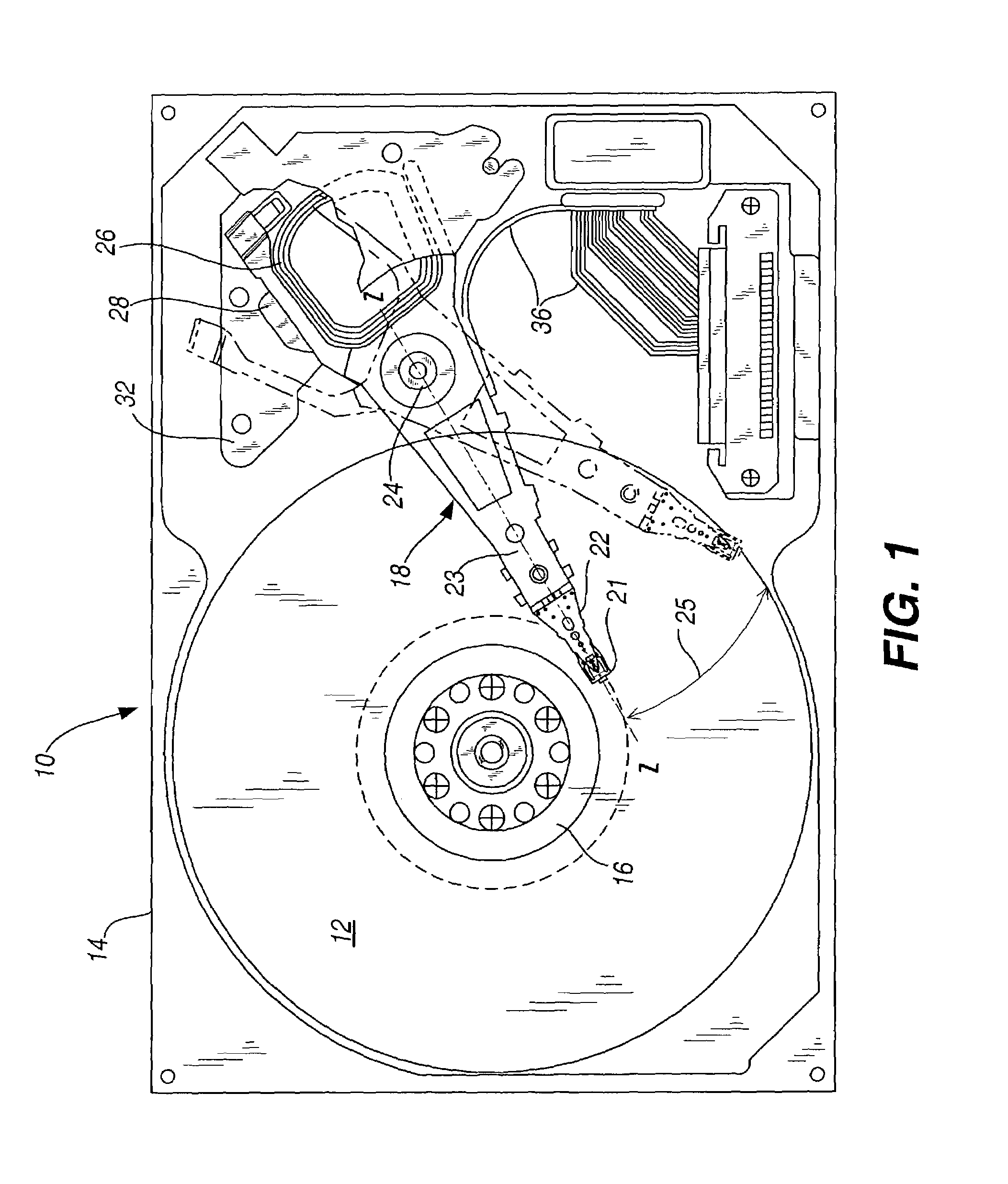
[0025]FIG. 1 shows a plan view of a standard disk drive assembly 10 with the top cover removed. FIG. 1 is representative of any number of common disk drives. The disk drive assembly 10 as illustrated includes at least one magnetic storage disk 12 typically having magnetic media on both upper and lower surfaces thereof. The disk 12 along with other components of the disk drive are contained within the housing 14. The disk 12 is mounted over a hub 16 which is driven by a motor (not shown) enabling the disk to rotate at high revolutions per minute during operation. An actuator assembly 18 is shown rotatably mounted to an actuator pivot 24. The actuator assembly extends along a longitudinal axis z—z. A load beam 22 connects to an actuator arm 23. A flexure 21 attaches to the load beam 22. In solid lines, the actuator assembly 18 is shown parked over the landing zone. The landing zone of the disk is allocated for takeoff and landing of the read / write heads during spin-up and spin-down of...


PUM


Abstract

A micro-flexure is provided for achieving secondary actuation in an actuator of a disk drive. The micro-flexure is a separate element which attaches to a standard flexure. A slider mounts to the micro-flexure. Piezoelectric elements attach to the micro-flexure to provide the motive force for displacing the micro-flexure during secondary actuation. The secondary actuation is thereby achieved by isolating movement at the slider.

Description

CROSS REFERENCE TO RELATED APPLICATIONS[0001]Priority is claimed from U.S. Provisional Patent Application Ser. No. 60 / 356,927, filed on Feb. 12, 2002, and entitled “MICRO-FLEXURE SUSPENSION DESIGN” and further identified as the disclosure of which is incorporated herein by reference in its entirety.FIELD OF THE INVENTION[0002]The present invention relates to actuators used in disk drives, and more particularly, to a micro-flexure suspension which provides secondary actuation thereby achieving finer head positioning.BACKGROUND OF THE INVENTION[0003]Computer disk drives typically incorporate retrieval and storage of data by use of magnetic storage disks and read / write heads which are capable of reading data from and writing data onto the rotating storage disks. Data is stored on each magnetic storage disk in a number of concentric tracks on the disk. The narrower the tracks can be made, the more data which can be stored on the storage disk. The read / write heads may also be referred to...

Claims


Application Information

Patent Timeline
IPC IPC(8): G11B5/55G11B5/60
CPCG11B5/5552
Inventor COFFEY, JERRY T.
Owner MAXTOR
Why Eureka
Try Eureka