Laser light source

a laser light source and laser light technology, applied in the direction of laser details, electrical equipment, excitation process/apparatus, etc., can solve the problems of unstable rate of population inversion of laser medium, unstable span of time from the start of pumping to the pulse laser oscillation time,

Inactive Publication Date: 2005-08-16
HAMAMATSU PHOTONICS KK
View PDF3 Cites 5 Cited by
  • Summary
  • Abstract
  • Description
  • Claims
  • Application Information

AI Technical Summary

Benefits of technology

[0015]Therefore, pulse laser light is outputted immediately after time T2 when the pumping of the laser medium effected by the pumping means becomes strong. As a consequence, even if the condition under which the pumping means pumps the laser medium is unstable, the control means can regulate the pulse laser li

Problems solved by technology

However, the above-mentioned conventional laser light sources using the passive Q-switching technique is problematic in that their operations at the time of starting the pumping and thereafter become unstable unless the condition under which the pumping means pumps the laser medium is stable.
Namely, if the condition under which the laser medium is pumped by the pumping means is unstable, the rate at which the popu

Method used


Image

  • Laser light source
  • Laser light source
  • Laser light source

Examples


first embodiment

(First Embodiment)

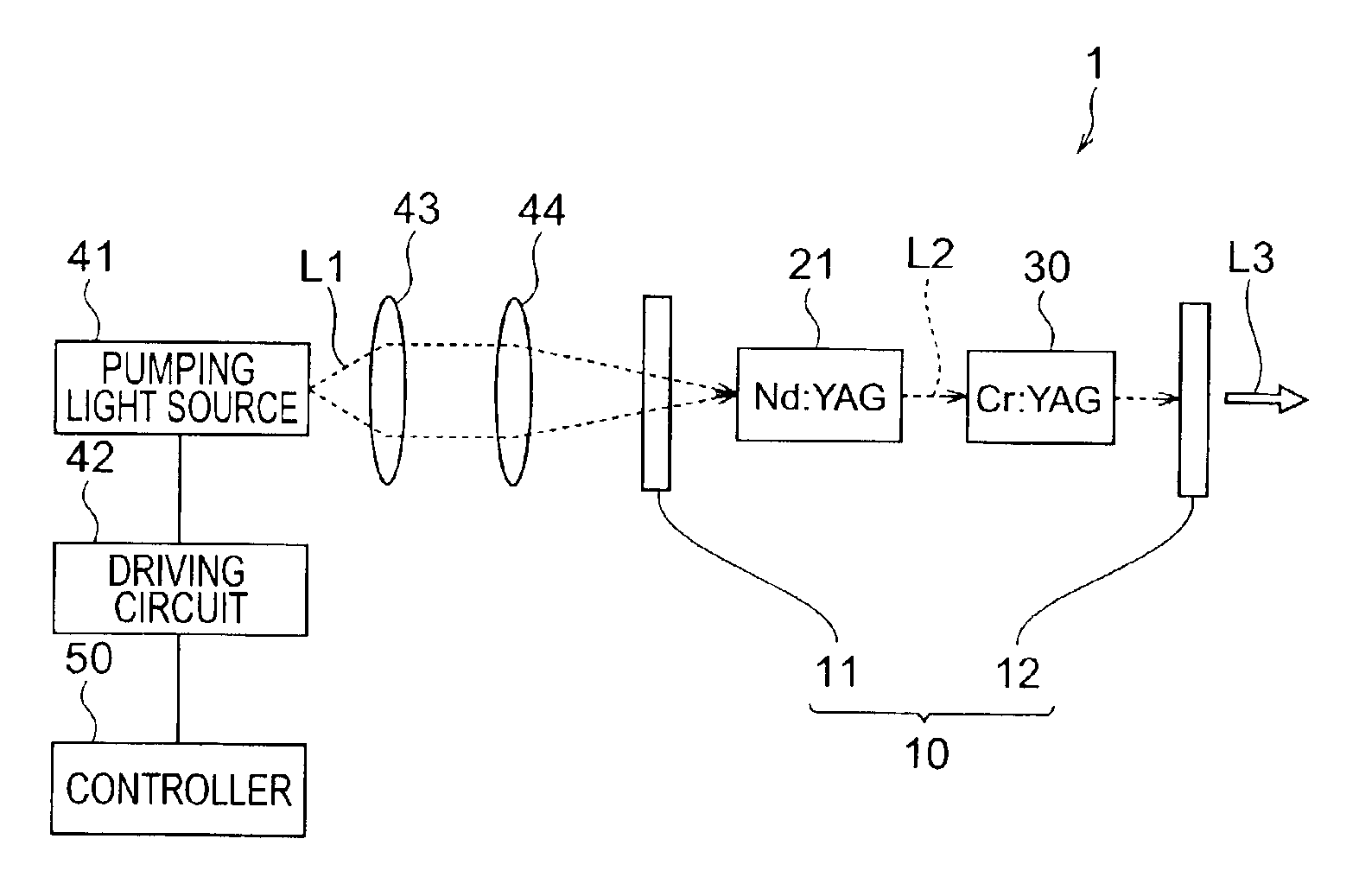
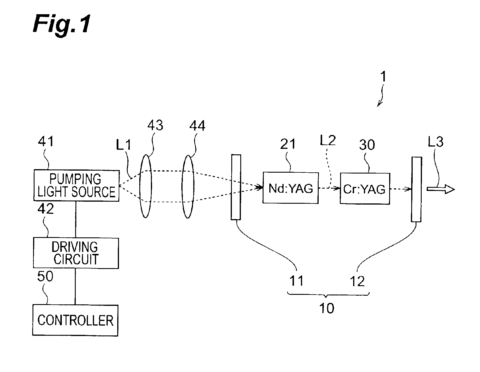
[0023]To begin with, a first embodiment of the laser light source in accordance with the present invention will be explained. FIG. 1 is a diagram of the laser light source 1 in accordance with the first embodiment. The laser light source 1 shown in this drawing comprises a resonator 10, a laser medium 21, a saturable absorber 30, a pumping light source 41, and a controller 50. The laser light source 1 comprises the pumping light source 41, a driving circuit 42, and lenses 43, 44 as pumping means for pumping the laser medium 21.

[0024]The resonator 10 has mirrors 11 and 12 opposing each other. One mirror 11 transmits therethrough pumping light L1 outputted from the pumping light source 41 but reflects at a high reflectance light L2 emitted from the pumped laser medium 21. The other mirror 12 transmits therethrough a part of the light L2 having arrived after being emitted from the pumped laser medium 21 and reflects the remainder. Light L3 transmitted through the mirr...

second embodiment

(Second Embodiment)

[0045]A second embodiment of the laser light source in accordance with the present invention will now be explained. FIG. 6 is a diagram showing the laser light source 2 in accordance with the second embodiment. The laser light source 2 shown in this drawing comprises a resonator 10, a laser medium 22, a pumping light source 41, and a controller 50. The laser light source 1 comprises the pumping light source 41, a driving circuit 42, and lenses 43, 44 as pumping means for pumping the laser medium 22.

[0046]The laser light source 2 in accordance with the second embodiment differs from that in accordance with the first embodiment in that the laser medium 22 also acts as a saturable absorber which is a Q-switching device. As the laser medium 22 also acting as a saturable absorber, NdCr:YAG crystal is preferably used, for example.

[0047]Though the mirrors 11 and 12 constituting the resonator 10 may be provided separately from the laser medium 22 as in the first embodimen...


PUM


Abstract

In the first period from pumping start time T1 to time T2 in a laser light source 1, the power of pumping light L1 outputted from a pumping light source 41 so as to irradiate a laser medium 21 is at value P1 whereas the power of light L2 incident on a saturable absorber 30 after being emitted from the laser medium 21 is at an absorption saturation threshold or lower, which causes a resonator 10 to lower its Q-value, thereby suppressing the laser oscillation. Immediately before time T2, the power of light L2 is slightly lower than the absorption saturation threshold. In the second period subsequent to the first period, the power of light L2 is at value P2 greater than the above-mentioned value P1, whereas the power of light L2 exceeds the absorption saturation threshold, which causes the resonator 10 to increase its Q-value, whereby a mirror 12 outputs pulse laser light L3 to the outside.

Description

BACKGROUND OF THE INVENTION[0001]1. Field of the Invention[0002]The present invention relates to a laser light source for outputting laser light with a high power and a short pulse by using the Q-switching technology.[0003]2. Related Background Art[0004]Laser light sources have been under study and development for attaining higher power, shorter pulse, and shorter wavelength in output light. In particular, attention has been directed toward laser light sources using the Q-switching technology. As a configuration having not only a laser medium but also a Q-switching device within a resonator, the Q-switching technology regulates the laser oscillation by changing the Q-value of resonator with the Q-switching device, thereby causing the laser light outputted therefrom to have a shorter pulse and a higher power.[0005]Various techniques have been known as the Q-switching technology. Among them, the passive Q-switching technique using a saturable absorber as a Q-switching device is prefer...

Claims


Application Information

Patent Timeline
IPC IPC(8): H01S3/11H01S3/102H01S3/0941H01S3/113
CPCH01S3/09415H01S3/1022H01S3/113H01S3/0612H01S3/0627H01S3/1024
Inventor KAN, HIROFUMISONE, AKIHIROSAKAI, HIROSHITAIRA, TAKUNORIPAVEL, NICOLAIELUPEI, VOICU
Owner HAMAMATSU PHOTONICS KK
Why Eureka
Try Eureka