
Vehicular steering device

a steering device and a technology for vehicles, applied in the direction of steering initiation, vessel construction, instruments, etc., can solve the problems of deteriorating vehicle stability and worsening of operation

Active Publication Date: 2005-08-16
TOYODA MASCH WORKS LTD +1
View PDF14 Cites 52 Cited by
  • Summary
  • Abstract
  • Description
  • Claims
  • Application Information

AI Technical Summary

Benefits of technology

The present invention provides a vehicular steering device that detects a grip factor of a steered wheel to improve vehicle stability on high μ roads. The device includes a steering means, a steering transmission system, a steering system, and a steered wheel. The device detects vehicle state quantities, changes the transfer ratio between the steering angle and the steered angle, detects at least one steering index, estimates self-aligning torque and steered wheel index, and judges whether the grip factor is less than a predetermined threshold value. The control means controls the electric motor accordingly to improve vehicle stability. The technical effect of the invention is to enhance the stability and control of the vehicle during high-speed driving.

Problems solved by technology

In this way, there is a problem that operability gets worse in an area where the stability of the vehicle deteriorates a little although a driver does not sense a danger since, conventionally, the IFS control is executed, for example, unnecessary counter steering is performed although the grip of the steered wheel is sufficient.

Method used


Image

  • Vehicular steering device
  • Vehicular steering device
  • Vehicular steering device

Examples


first embodiment

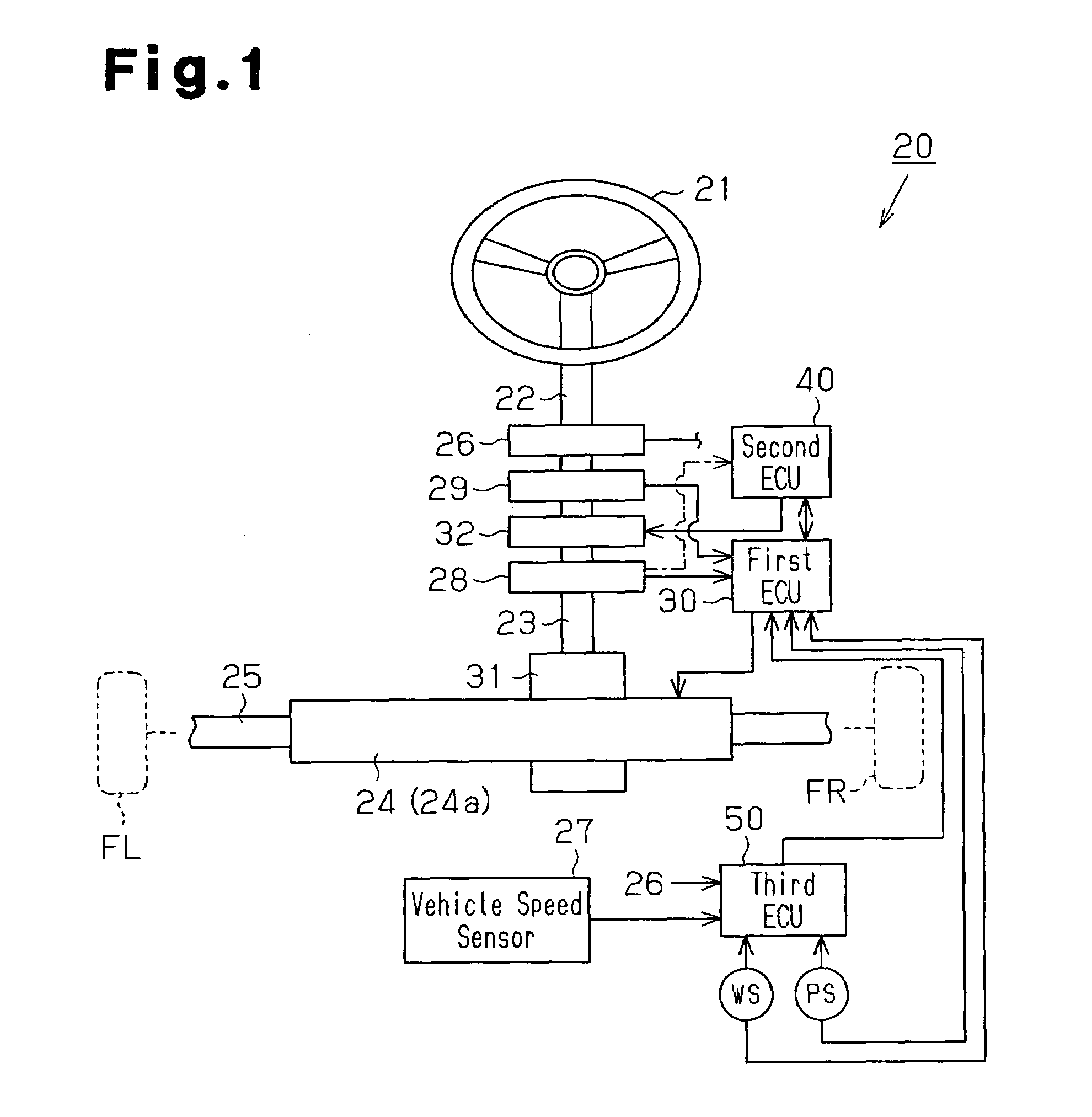
[0035]Hereafter, a first embodiment will be explained with reference to FIGS. 1 to 13.

[0036](1) Hardware Constitution of Steering Device 20

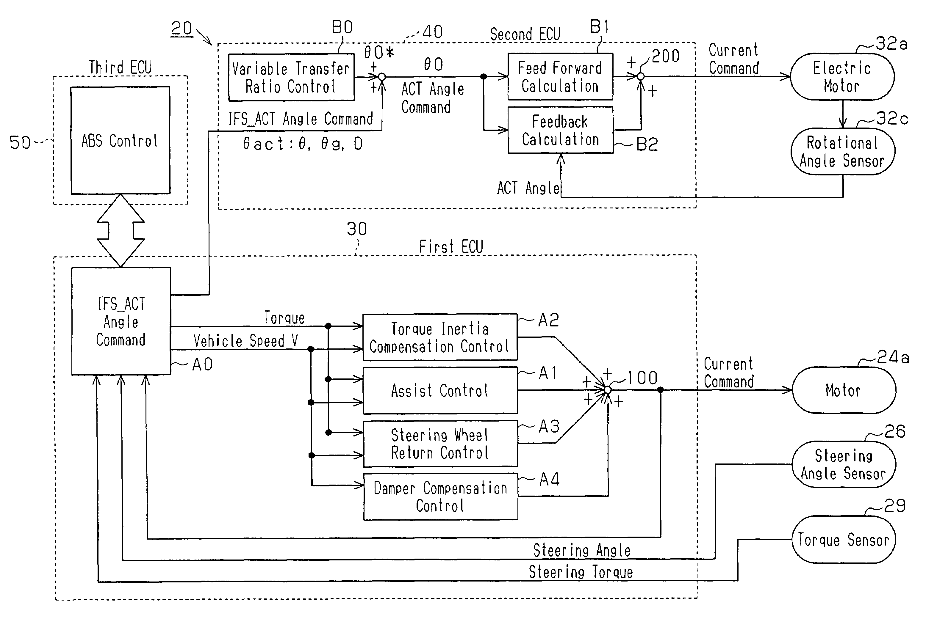
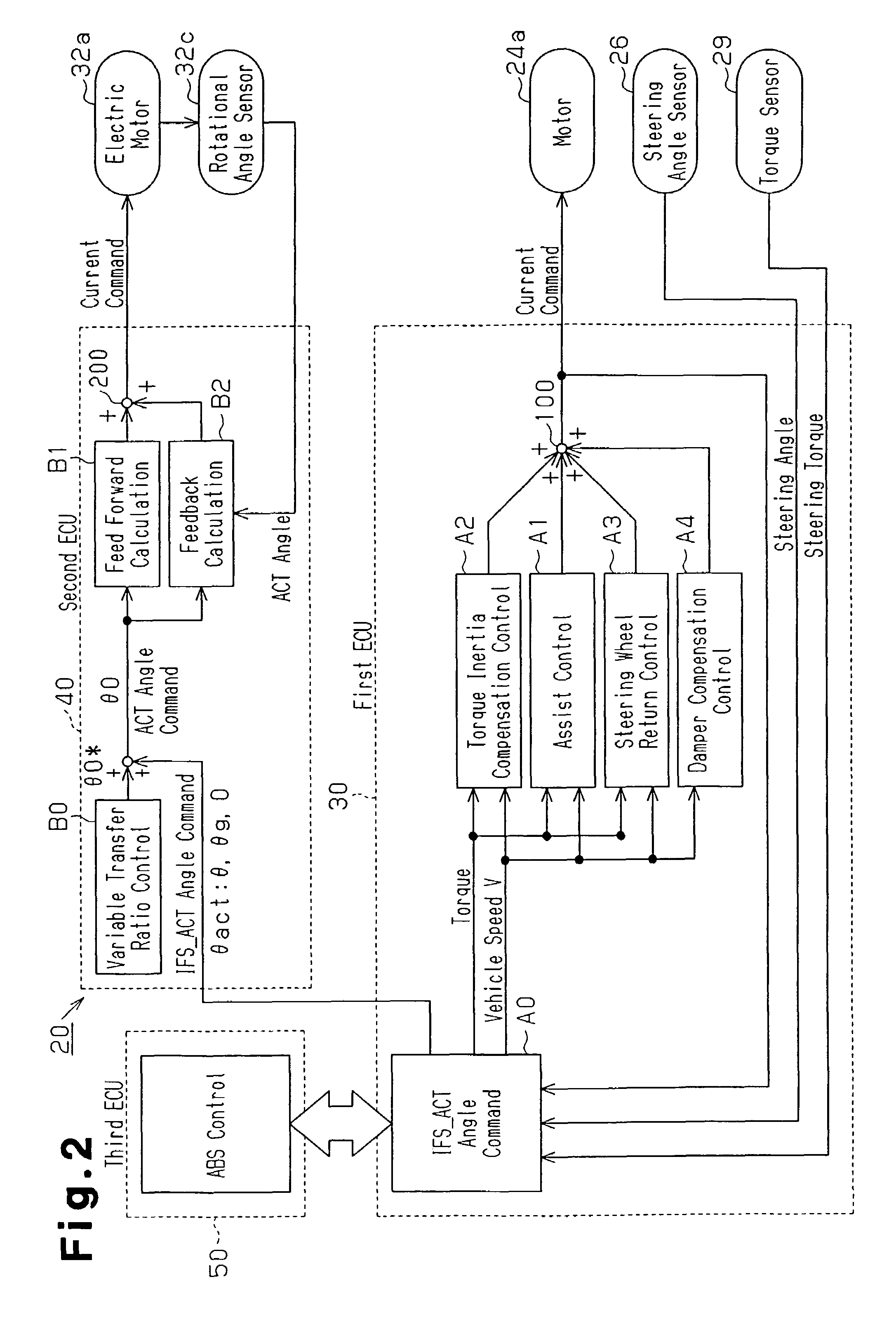
[0037]As shown in FIG. 1, the steering device 20 comprises a steering wheel 21, a first steering shaft 22, a second steering shaft 23, a rod 25, a steering angle sensor 26, an output angle sensor 28, a steering torque sensor 29, and an IFS actuator 32. Thus, an end of the first steering shaft 22 is connected to the steering wheel 21. An input side of the IFS actuator 32 is connected to the first steering shaft 22. The steering wheel 21 is equivalent to the steering means. In addition, IFS stands for Intelligent Front Steer. The IFS actuator 32 comprises an electric motor 32a (refer to FIG. 4) and a reducer, one end of the second steering shaft 23 is connected to its output side, and an input side of a steering gear box 31 is connected to another end of the second steering shaft 23. The steering gear box 31 comprises a rack-and-pinion gear which i...

second embodiment

[0185]A second embodiment will be explained with reference to FIGS. 15 to 20. The same reference numerals and characters will be assigned to the parts which are the same as or corresponds to those in the first embodiment, their explanation will be omitted, and different parts will be explained mainly. The second embodiment relates to another aspect of estimation of the grip factor, and a front wheel slip angle is used as a front wheel index of the present invention.

[0186]FIG. 15 is a block diagram of means for estimating the grip factor from the front wheel slip angle and a self-aligning torque. Reference characters M1 to M6 are the same as those in the first embodiment, a reactive torque and steering system friction torques will be calculated, and a self aligning torque will be estimated. On the other hand, since a front wheel slip angle is calculated from a steering angle, a yaw rate, lateral acceleration, and vehicle speed, similarly to FIG. 14 in the first embodiment, detection ...


PUM


Abstract

A first ECU 30 detects a steering torque applied to a steering system, estimates a self-aligning torque generated in a front wheel on the basis of the steering torque, and estimates a side force for the front wheel on the basis of lateral acceleration and a yaw rate. The first ECU 30 estimates a grip factor ε for the front wheel on the basis of a change of the self-aligning torque to the side force. The first ECU 30 judges whether the grip factor is below a second OS (oversteer) start threshold value. A second ECU 40 controls the transfer ratio according to the vehicle state when the grip factor is less than the second OS start threshold value.

Description

CROSS-REFERENCE TO RELATED APPLICATIONS[0001]This application is based upon and claims the benefit of priority from prior Japanese Patent Application No. 2003-321872, filed on Sep. 12, 2003, the entire contents of which are incorporated herein by reference.BACKGROUND OF THE INVENTION[0002]The present invention relates to a vehicular steering device comprising a unit, which changes a transfer ratio between a steering angle of a steering wheel and a steered angle of a steered wheel, in a steering transmission system which couples a steering member, such as the steering wheel, and the steered wheel by the drive of an electric motor.[0003]Up to now, for the purpose of the progress in drivability and safety of a vehicle, for example, an intelligent front steering control (IFS control) has been proposed, the intelligent front steering control which steers a steered wheel (front wheel) by detecting vehicle state quantities such as a yaw rate and a car body slip angle, and feeding back the ...

Claims


Application Information

Patent Timeline
Patent Type & Authority Patents(United States)
IPC IPC(8): B62D5/00B62D6/00B60T8/17B60T8/172B62D101/00B62D103/00B62D111/00B62D113/00B62D119/00B62D137/00
CPCB60T8/172B62D5/008B62D6/003B62D6/006B60T2210/12B60T2220/03
Inventor KATO, HIROAKIMOMIYAMA, MINEKAZUOHTA, TAKAYUKIYASUI, YOSHIYUKIIMOTO, YUZOAIZAWA, HIROAKIONO, EIICHIMURAGISHI, YUJI
Owner TOYODA MASCH WORKS LTD
Learn More