Apparatus for and method of calculating electromagnetic field intensity, and computer program product

a technology of electromagnetic field intensity and apparatus, applied in the direction of resistance/reactance/impedence, testing circuit, instruments, etc., can solve the problem that the intensity of electromagnetic field cannot be calculated using wave source power

Active Publication Date: 2005-08-16
FUJITSU LTD +1
View PDF2 Cites 2 Cited by
  • Summary
  • Abstract
  • Description
  • Claims
  • Application Information

AI Technical Summary

Problems solved by technology

However, the conventional art is a technique constituted to calculate an electromagnetic field intensity by solving the determinant so as to meet such a boundary condition that the electric field on a metal surface is zero, where there is a problem that the electromagnetic field intensity can not be calculated using wave source power.

Method used


Image

  • Apparatus for and method of calculating electromagnetic field intensity, and computer program product
  • Apparatus for and method of calculating electromagnetic field intensity, and computer program product
  • Apparatus for and method of calculating electromagnetic field intensity, and computer program product

Examples


first embodiment

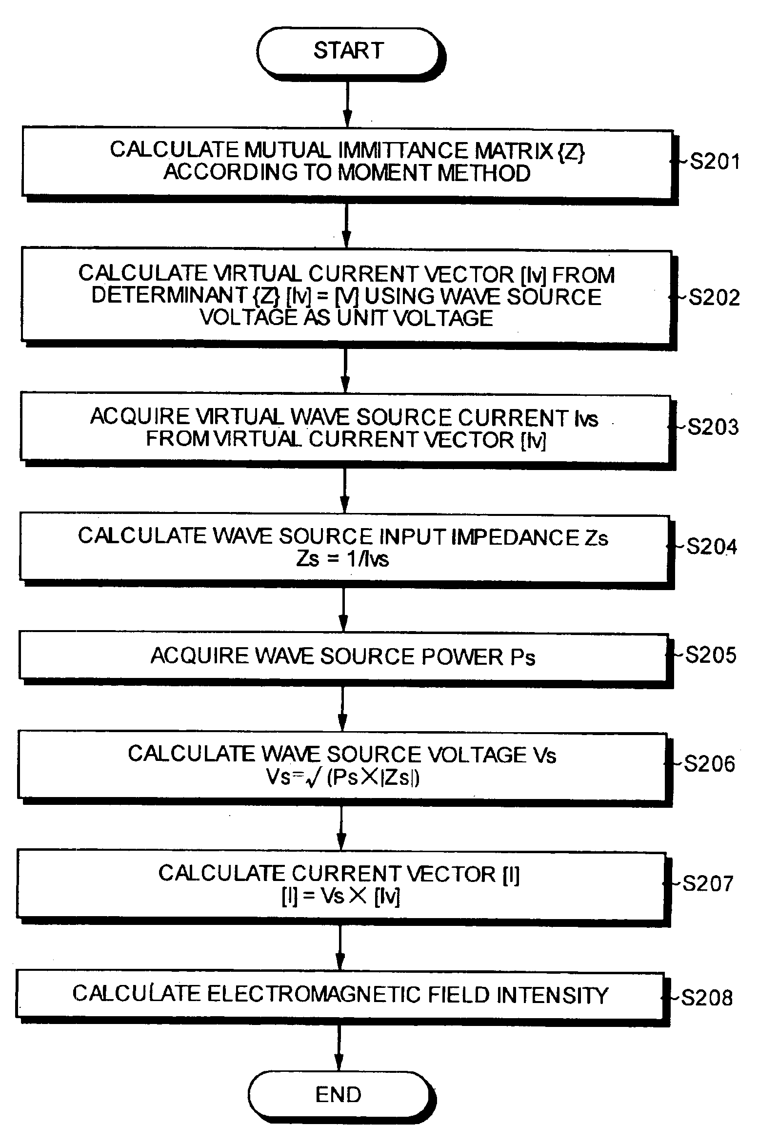
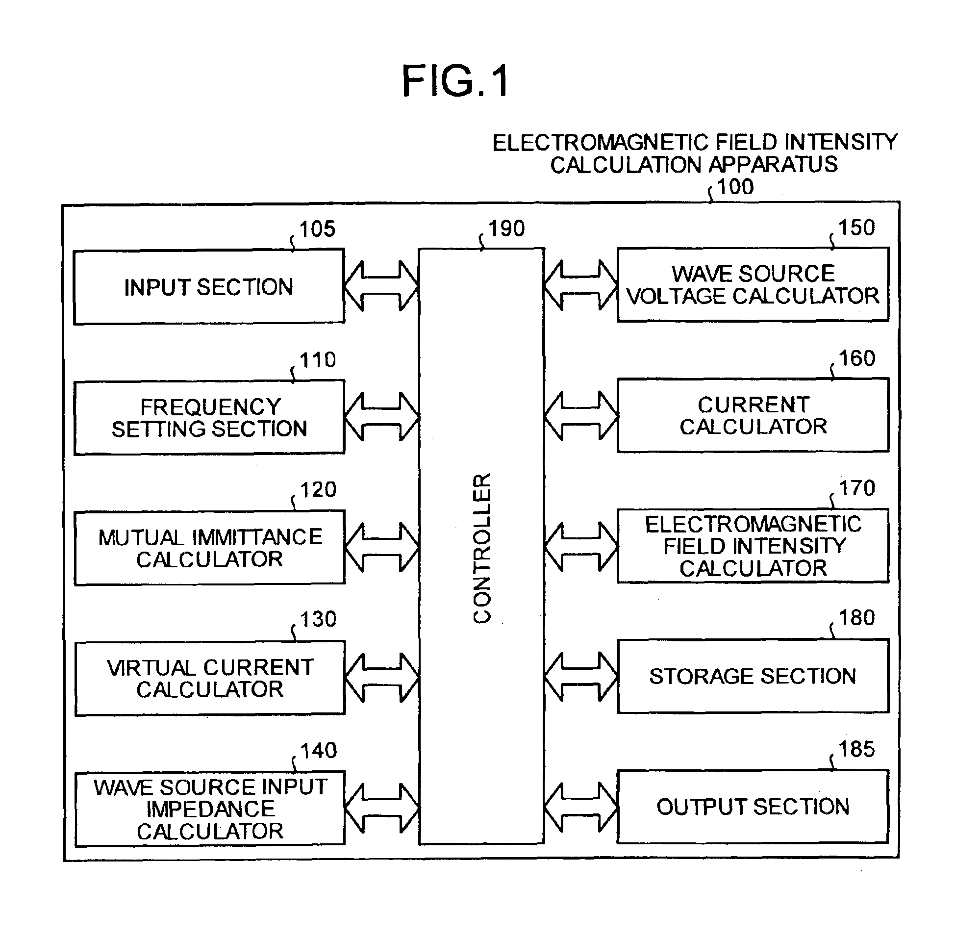
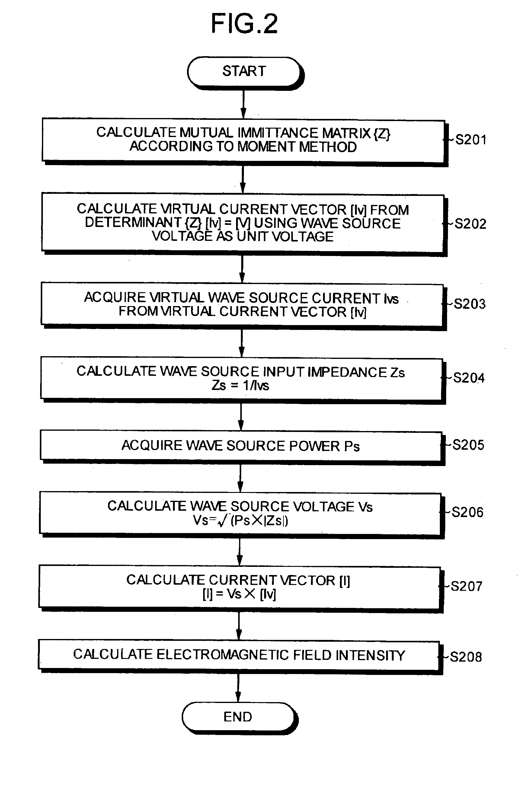
[0024]The configuration of the electromagnetic field intensity calculation apparatus will be explained. As illustrated in FIG. 1, the electromagnetic field intensity calculation apparatus 100 is an apparatus which applies the moment method to an analysis model where an object has been divided into a finite number of small elements and solves a determinant {Z}=[I]=[V] established among the calculated mutual immittance matrix {Z}, a voltage vector [V], and a current vector [I] to obtain the current vector [I], thereby calculating an electromagnetic field intensity radiated from the object.

[0025]Specifically, the electromagnetic field intensity calculation apparatus 100 includes an input section 105, a frequency setting section 110, a mutual immittance calculator 120, a virtual current calculator 130, a wave source input impedance calculator 140, a wave source voltage calculator 150, a current calculator 160, an electromagnetic field intensity calculator 170, a storage section 180, an...

second embodiment

[0046]FIG. 4 is a system configuration diagram illustrating a configuration of a computer system and FIG. 5 is a block diagram illustrating a configuration of a main body in the computer system. As illustrated in FIG. 4, a computer system 200 according to this embodiment includes a main body 201, a display 202 for displaying information such as an image on a display screen 202a according to an instruction from the main body 201, a key board 203 for inputting various pieces of information into the computer system 200, and a mouse 204 for pointing an arbitrary position on the display screen 202a of the display 202.

[0047]As illustrated in FIG. 5, the main body 201 in the computer system 200 includes a Central Processing Unit (hereinafter,“CPU”) 221, a Random Access Memory (hereinafter, “RAM”) 222, a Read Only Memory (hereinafter, “ROM”) 223, a Hard Disk Drive (hereinafter, “HDD”) 224, a CD-ROM drive 225 receiving a CD-ROM 209, a Flexible Disk (hereinafter, “FD”) drive 226 receiving an...


PUM


Abstract

An electromagnetic field intensity calculation apparatus calculates a virtual current vector from a voltage vector and a mutual immittance matrix of an object including a wave source where a wave source power is applied. The voltage vector and the mutual immittance use a wave voltage of the wave source as a unit voltage. The apparatus also calculates an input impedance of the wave source based on a virtual wave source current of the virtual current vector and a unit voltage of the wave source, and calculates the wave source voltage based on the input impedance and the wave source power. The apparatus further calculates a current vector based on the wave source voltage calculated and the virtual current vector, and calculates an electromagnetic field intensity around the wave source which is determined based on the current vector.

Description

BACKGROUND OF THE INVENTION[0001]1) Field of the Invention[0002]The present invention relates to an apparatus for and a method of calculating electromagnetic field intensity in which, when a wave source power is applied, an electromagnetic field intensity can be calculated based on a moment method.[0003]2) Description of the Related Art[0004]Conventionally, an electromagnetic field intensity calculation apparatus that calculates an electromagnetic field intensity around a wave source applied with a wave source power based on a current vector calculated using a mutual immittance matrix of a subject having a wave source and a voltage vector is known. Such an electromagnetic field intensity calculation apparatus applies a moment method to an integral equation derived from Maxwell electromagnetic wave equation to calculate a current of a three-dimensional object with any shape through a numerical analysis.[0005]Specifically, an object is divided into a finite number of small elements, t...

Claims


Application Information

Patent Timeline
Patent Type & Authority Patents(United States)
IPC IPC(8): G01R27/00G01R29/08G01R33/00G06F19/00G06F17/50
CPCG06F17/5036G06F30/367
Inventor YOSHIDA, HIROSHIOHTAKE, MASAMICHIHAYAKAWA, YASUHIROMATSUBARA, YASUONAGASE, KENJIYAMAGAJO, TAKASHI
Owner FUJITSU LTD
Why Eureka
Try Eureka