Method of connecting multi conductor cable connector

a multi-conductor cable and connector technology, applied in the field of electric connectors, can solve the problems of few applications for this technology for flat conductor cables, low current carrying capacity, and inability to meet the needs of the customer, and achieve the effect of increasing the current carrying capacity

Inactive Publication Date: 2005-08-23
MIRACO
View PDF4 Cites 11 Cited by
  • Summary
  • Abstract
  • Description
  • Claims
  • Application Information

AI Technical Summary

Benefits of technology

[0014]This invention results from the realization that an IDC can be made more compact than previously available connectors by using a more narrow contact for each conductor in the multi-conductor cable, can be made more convenient by enabling all conductors contained in the multi-conductor cable to be connected with a single user motion, and can connect to multi-conductor cable without damaging the mechanical or electrical integrity of the cable conductors.

Problems solved by technology

Failure to meet the tolerances will result in rejected product, lost time, and lost money.
Until now, there have been few applications for this technology for flat conductor cables.
One such limitation is that the contact pierces through the insulation on both sides of the cable.
This limitation has several inherent problems.
The first problem is that the insulation distance or “spacing” between the conductors has been decreased.
A decrease in spacing will reduce the high-voltage carrying capacity of the system and may cause short circuiting failures.
The second problem is that piercing through the insulation weakens it, and may cause it to tear and expose an air gap between adjacent conductors, also decreasing the high-voltage carrying capacity of the system.
This problem would especially cause concern when using polyimide insulation materials, which have a lower tear resistance than polyester materials.
Another problem emerges when the copper conductor is folded during the engagement of the contact and the conductor.
Since copper is a ductile material, it does not provide enough spring resistance and will create an unreliable electrical contact as the copper relaxes over time and reduces the contact pressure at the connection point.
Also, if the conductor does not fold, it will be either damaged or broken.
One of these types pierces through both the insulation and the copper conductor, which damages the conductor and reduces its current carrying capacity.
As previously described, the piercing of the insulation both reduces the spacing between conductors and weakens the insulation, which may tear.
If the crimping process is not performed properly and consistently, the contact system will be unreliable.
Also, this type of connection leaves the conductive material of the contact exposed on the outside of the cable with only an air gap to provide electrical insulation between the conductors, limiting the high-voltage carrying capacity of the system.
A fourth problem is that in many of these designs the contacts either intentionally or unintentionally may pierce through both the protective surface plating and copper conductors of the multi-conductor cable.
Motion at the connection points may expose this copper to the environment and copper oxides may form which will propagate and eventually contaminate the connection causing a short or open circuit failure.
With all of the above-described designs, the conductor density is severely limited due to the space required to provide a contact that is sufficiently strong to provide the minimum contact force for a gas-tight connection.
Many of these designs require a large spacing between the conductors and are not capable of being used in newer system designs, which require much higher density connectors.
Also, the multi-conductor cable density is impaired by the required piercing of insulation between conductors instead of making contact with the conductors on their wider surface.

Method used


Image

  • Method of connecting multi conductor cable connector
  • Method of connecting multi conductor cable connector
  • Method of connecting multi conductor cable connector

Examples


Embodiment Construction

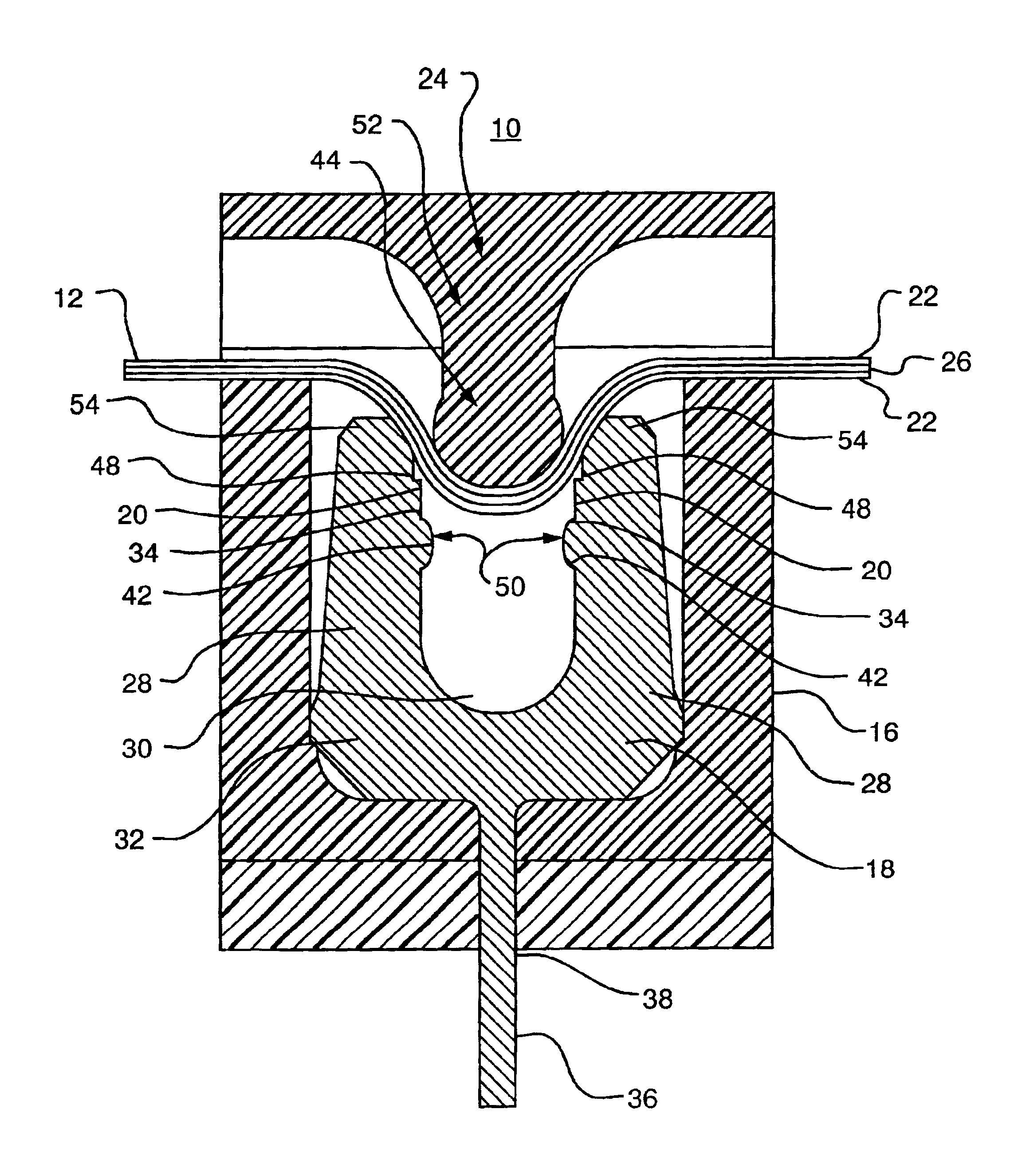
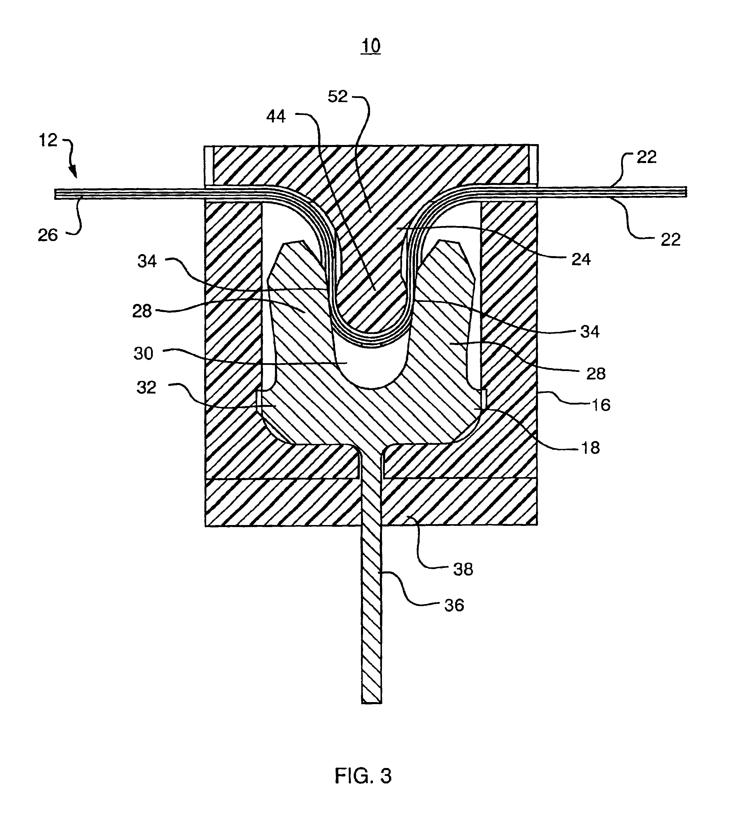
[0042]This invention is an electrical connector 10, shown in FIG. 3, for connecting multi-conductor cable 12. Multi-conductor cable 12 is cable such as flat flexible cable, printed circuits, and similarly constructed cables wherein the cross-section of the conductor 26 has a width dimension 13 greater than the thickness dimension 14. The surface of each conductor 26. The inventive electrical connector 10 has a base 16 for holding multiple contacts 18. The contacts 18 should be positioned substantially in parallel with each other and are located at least partially within the base 16 of the electrical connector 10. Each contact 18 has at least one insulation-displacing surface 34. The insulation-displacing surface 34 is preferably a part of the contact 18 and is oriented to remove insulation 22 from along the width dimension 13 of the conductors 26, described as a width surface 15. The final part of the electrical connector 10, in one of its broadest embodiments, is an actuator 24, in...


PUM

PropertyMeasurementUnit
depthaaaaaaaaaa
electrical contact forceaaaaaaaaaa
insulatingaaaaaaaaaa

Abstract

This invention is an electrical connection method for connecting multiple conductor cable, ideally flat flexible cable. The method involves using an actuator for pressing the cable against multiple contacts in a base, each of which contacts has a sharp edge for removing insulation from the cable.

Description

[0001]The present application claims benefit as a divisional application from the previously filed parent application, U.S. patent application Ser. No. 09 / 843,317, filed Apr. 25, 2001, now U.S. Pat. No. 6,394,833, issued May 28, 2002.FIELD OF THE INVENTION[0002]This invention relates to the field of electrical connectors. Specifically, this invention relates to the field of electrical connectors for multi-conductor cable.BACKGROUND OF THE INVENTION[0003]The present invention is an Insulation Displacement Connector (IDC) for use with multi-conductor cable, such as Flat Flexible Cable (FFC) and Flexible Printed Circuits (FPC) which would provide the same convenience, cost savings, and long-term reliability that has been available for solid conductor round wire connections using the “U” form contact for over two decades. The result is a design that successfully translates IDC technology used for round wire interconnects to flat conductor systems.[0004]The “U” form IDC contact was origi...

Claims


Application Information

Patent Timeline
Patent Type & Authority Patents(United States)
IPC IPC(8): H01R12/00H01R12/08H01R4/24H01R43/01H01R43/04H01R12/67H01R12/79
CPCH01R12/675H01R12/79Y10T29/49181Y10T29/49174Y10T29/49208Y10T29/53209Y10T29/49218H01R4/24
Inventor BULMER, DOUGLAS R.ROBERTS, II, JOSEPH A.
Owner MIRACO
Why Eureka
Try Eureka