Apparatus and methods for measuring the pin diameter of a crankshaft at the place of grinding

a crankshaft and crankshaft technology, applied in the direction of feeding apparatus, rigid containers, program control, etc., can solve the problems that the known apparatus does not enable the automatic and sequential machining of parts, and achieve the effect of improving the sensitivity of the head, widening the measurement range, and improving the resolution of the apparatus

Inactive Publication Date: 2005-08-23
MARPOSS SPA
View PDF32 Cites 31 Cited by
  • Summary
  • Abstract
  • Description
  • Claims
  • Application Information

AI Technical Summary

Benefits of technology

[0005]Object of the present invention is to provide an apparatus for the checking of pins rotating in the course of the machining in a machine tool, for example during the in-process checking in a grinding machine for grinding crankpins rotating with an orbital motion and / or main journals rotating about their symmetry axis, that enables to check in a simple and rapid way pins having nominal diametral dimensions varying within a relatively wide range.
[0007]Thus, by compensating transducer errors, it is possible to attain a wide transducer linearity range and corresponding measurement displacements of the feeler of a considerable entity. In this way, the choice for determining the appropriate angle defined by the sides of the Vee-shaped reference device, permitting the head to have a wide measurement range, is not substantially bound to the need of limiting the feeler displacements but it can be made by taking into due consideration other physical or functional characteristics of the application.
[0008]Moreover, wider feeler displacements enable to achieve, at an identical measurement range, an improved sensitivity of the head and a higher resolution of the apparatus.

Problems solved by technology

However, these known apparatuses do not enable to check in an automatic and sequential way the machining of parts differing among each other insofar as their nominal dimensions are concerned (for example the crankpins and the main journals of a same crankshaft), as this would imply the need to replace the Vee-shaped reference devices in between a checking and a subsequent one or at least carry out a new head calibration on a suitable section of a master piece every time the nominal dimension changes.

Method used


Image

  • Apparatus and methods for measuring the pin diameter of a crankshaft at the place of grinding
  • Apparatus and methods for measuring the pin diameter of a crankshaft at the place of grinding
  • Apparatus and methods for measuring the pin diameter of a crankshaft at the place of grinding

Examples


Embodiment Construction

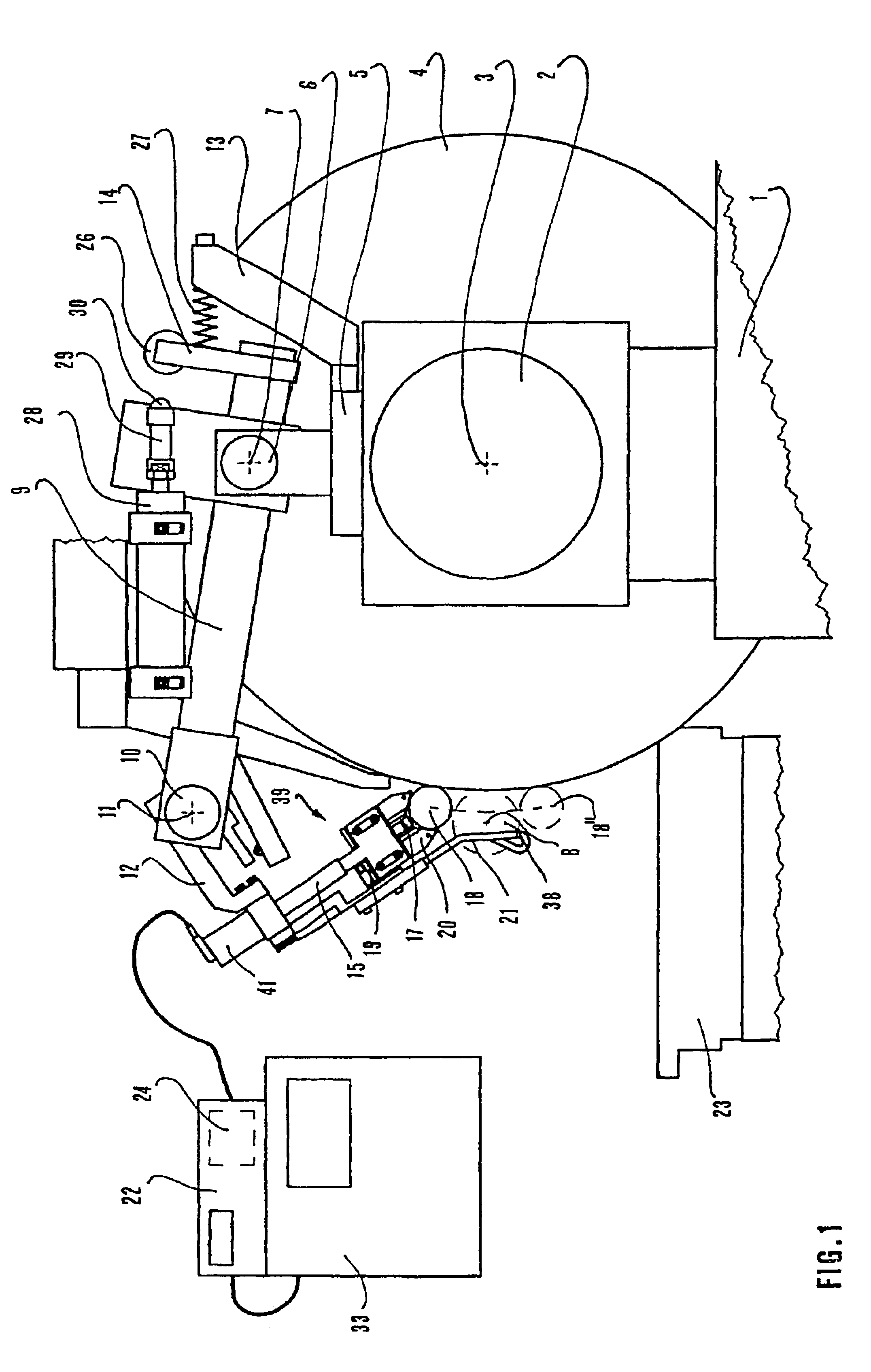
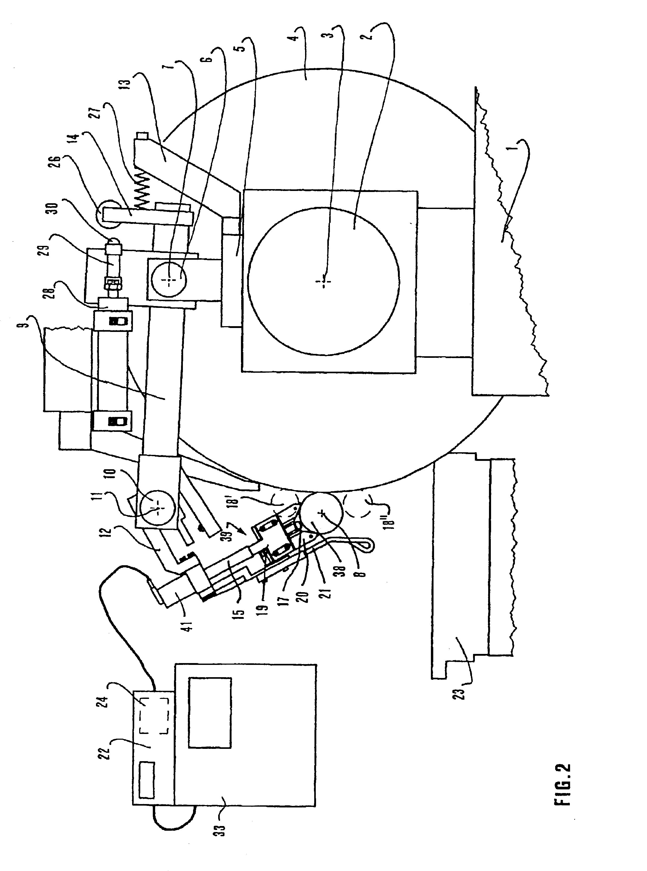
[0017]With reference to FIGS. 1 to 3, the grinding wheel slide 1 of a computer numerical control (“CNC”) grinding machine—for grinding a crankshaft 34 defining an axis of rotation 8—supports a spindle 2 that defines the axis of rotation 3 of grinding wheel 4. Above spindle 2 the grinding wheel slide 1 carries a support device including a support element 5 and a first rotating, coupling element 9 and a second rotating, coupling element 12. The support element 5, by means of a rotation pin 6 that defines a first axis of rotation 7 parallel to the axis of rotation 3 of grinding wheel 4 and the axis of rotation 8 of the crankshaft 34, supports the first rotating, coupling element 9.

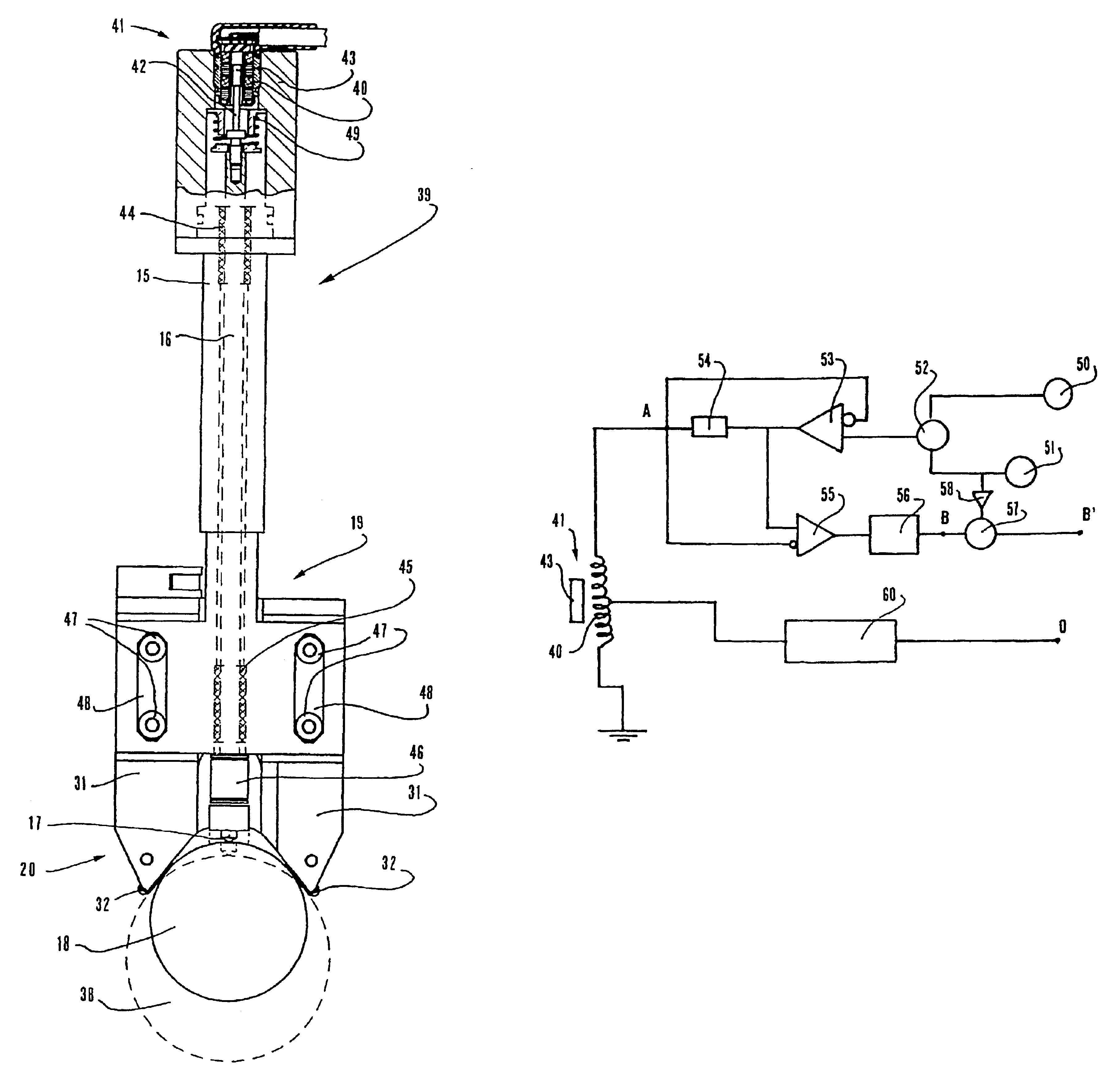
[0018]In turn, coupling element 9, by means of a rotation pin 10, defining a second axis of rotation 11 parallel to the axis of rotation 3 of grinding wheel 4 and to the axis of rotation 8 of the crankshaft 34, supports the second rotating, coupling element 12. At the free end of coupling element 12 there is ...


PUM


Abstract

An apparatus for checking diametral dimensions of crankpins and main journals in the course of grinding is provided. The apparatus includes a head with a Vee-shaped reference device and an axially movable feeler that contacts the surface of the pin to be checked, and an articulated support device, coupled to the grinding wheel slide that carries the head and enables it to keep contact with the surface of the pin during possible orbital rotations. A transducer in the head cooperates with the feeler for detecting its displacements and transmits signals to a processing and display device in turn connected with the computer numerical control of the grinding machine. The processing and display device processes the transducer signals with compensation values or coefficients stored in a memory unit for obtaining measuring signals output by the head that vary in a linear way in a wide range and for compensating errors due to temperature variations.

Description

TECHNICAL FIELD[0001]The invention relates to an apparatus for checking the diameter of pins, rotating about a geometrical axis, in the course of the machining in a numerical control grinding machine including a worktable, defining said geometrical axis and a grinding wheel slide carrying a grinding wheel, with a measuring head including a Vee-shaped reference device for cooperating with the pins to be checked, a feeler for contacting the surfaces of the pins to be checked and performing translation displacements substantially along the bisecting line of the Vee-shaped reference device, and a transducer for generating signals depending on the position of the feeler with respect to the Vee-shaped reference device, a support device, adapted to be coupled to the grinding wheel slide, including reciprocally movable coupling elements, for supporting the measuring head in a movable way, a control device for controlling automatic displacements of the measuring head from a rest position to ...

Claims


Application Information

Patent Timeline
Patent Type & Authority Patents(United States)
IPC IPC(8): B24B5/00B24B49/02B24B49/00B24B5/42B24B49/04B24B49/14B24B51/00B23Q15/18B23Q17/20G01B21/10B65D85/10G01B5/08G05B19/404
CPCB24B5/42B24B49/04G01B5/08
Inventor DALL'AGLIO, CARLO
Owner MARPOSS SPA
Why Eureka
Try Eureka