Swaging technology

a technology of swaging and forming, applied in the direction of forging presses, prosthesis, shaping safety devices, etc., can solve the problems of limitations and shortcomings of existing technology, and achieve the effect of reliable, practical, accurate and efficien

Inactive Publication Date: 2005-08-23
MACHINE SOLUTIONS
View PDF12 Cites 45 Cited by
  • Summary
  • Abstract
  • Description
  • Claims
  • Application Information

AI Technical Summary

Benefits of technology

[0015]The present invention provides a swaging system, apparatus and method which are practical, reliable, accurat...

Problems solved by technology

Existing technology is believed...

Method used


Image

  • Swaging technology
  • Swaging technology
  • Swaging technology

Examples


Embodiment Construction

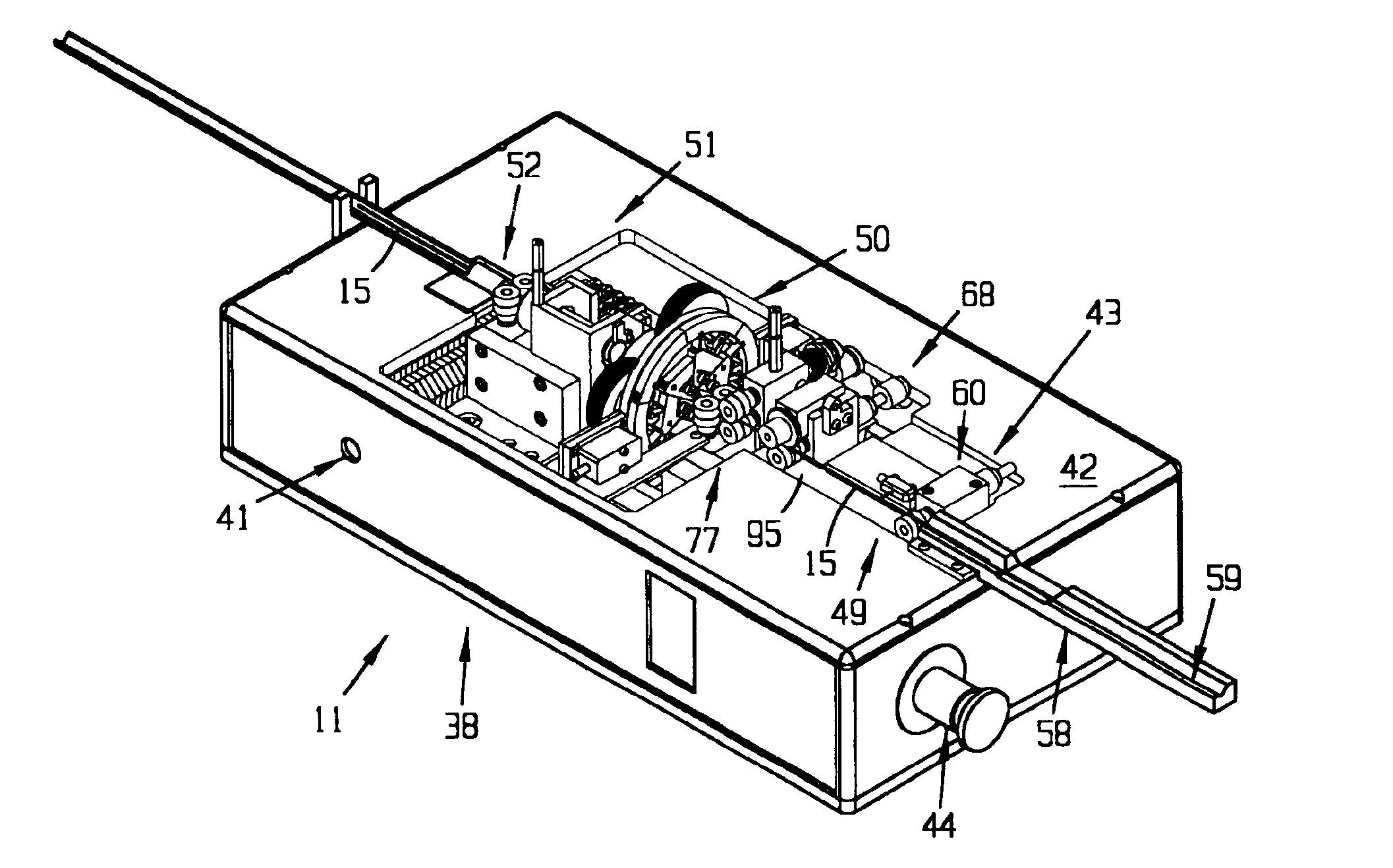
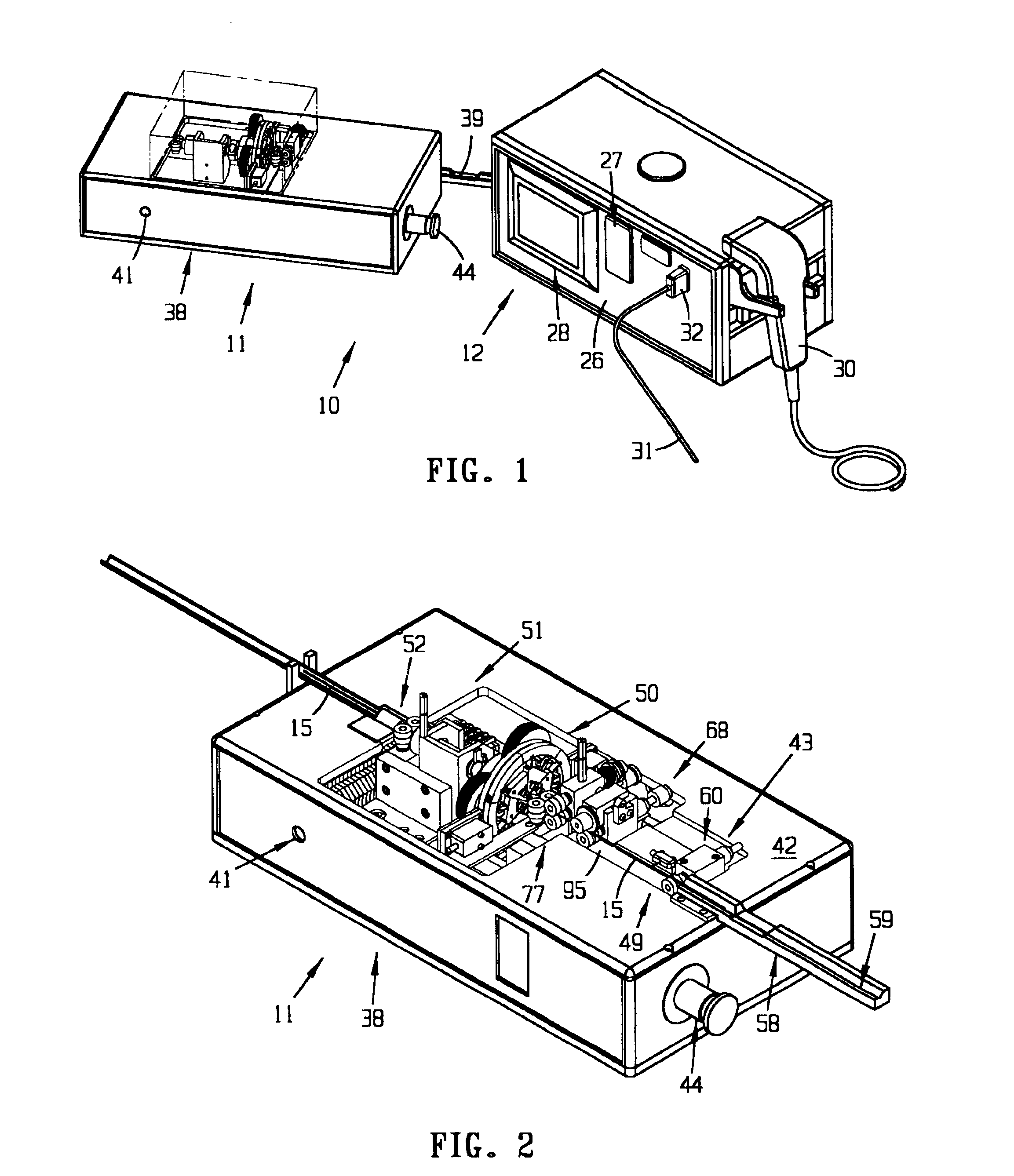
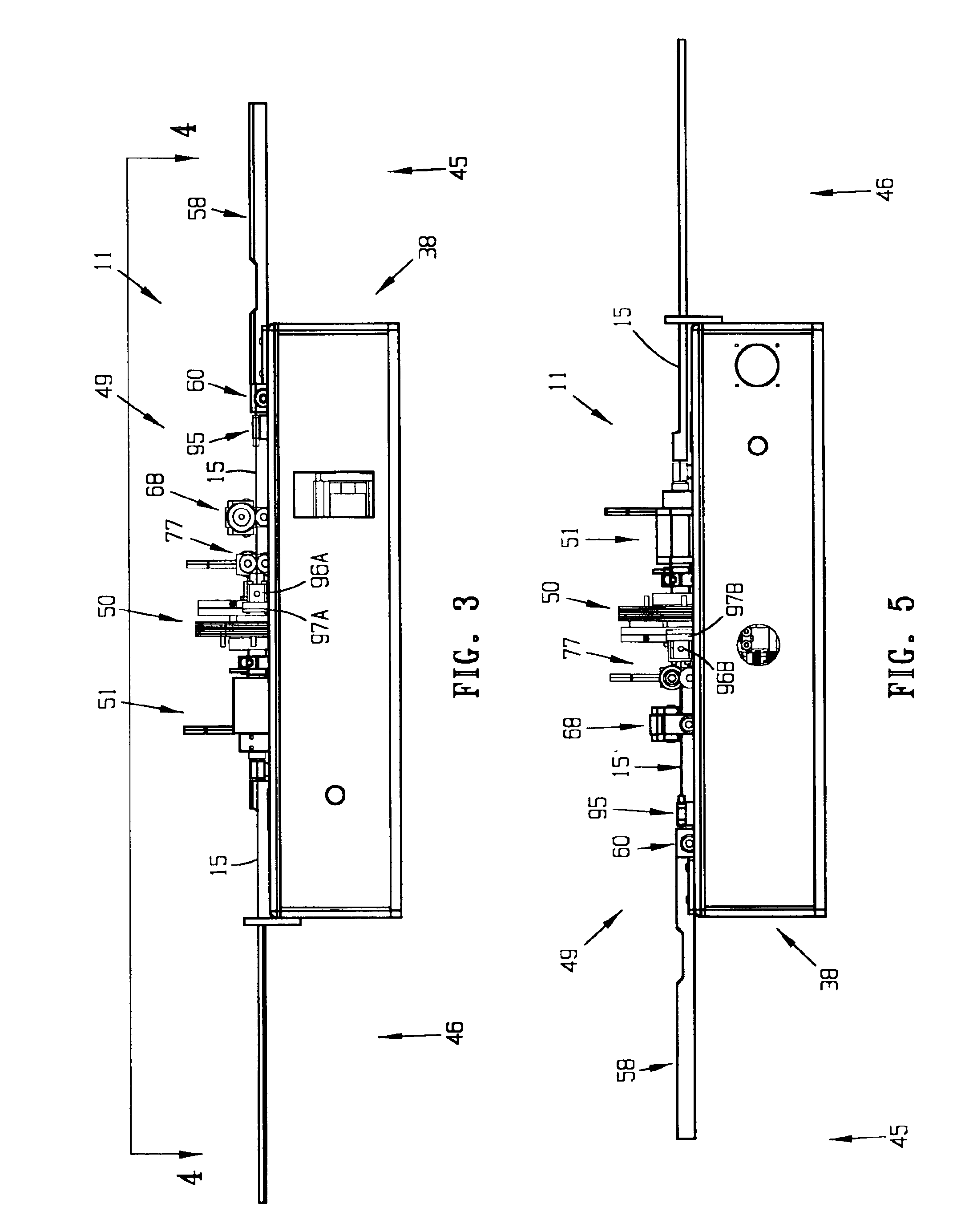
[0057]The drawing Figures show preferred embodiments of the swaging system or swager 10, components thereof, and process of present invention. The swager system 10 is described below first in terms of its major structural elements and then in terms of its secondary structural and / or functional elements which cooperate to perform the preferred swaging function. The embodiments of the invention described are intended to be illustrative and not to be exhaustive or limit the invention to the exact forms disclosed. The embodiments are chosen and described so that persons skilled in the art will be able to understand the invention and the manner and process of making and using it.

[0058]The swaging system, apparatus and process is useful for connecting one material element, a swaged element, to another material element, a base element. In particular, it is useful for swaging bands, for example metal bands, to tubular structures, for example polymeric tubular structures, in a precise, subst...


PUM

PropertyMeasurementUnit
Forceaaaaaaaaaa

Abstract

A swager for swaging marker bands to a medical catheter, comprises an article input mechanism, the article input mechanism having a first input roller assembly for receiving and conveying an article, a first sensor for detecting a predetermined aspect of the article, a second input roller assembly for receiving and conveying the article, a positioning roller assembly for precisely aligning the article with respect to the swaging head, and a second sensor all constructed and arranged in a streamwise orientation. The swager also has a radial compression swaging head with a central swaging aperture, the swaging head being aligned and communicatively coupled with the input mechanism to receive an input article from the article input mechanism and to swage the article, the swaging head being rotatable and including (i.) a unitary die plate including a plurality of die segments movably coupled to each other to provide a radial compressive force to the article disposed in the central swaging aperture; and (ii.) a closing plate pivotally coupled with respect to each other. The swager also has an output mechanism aligned and communicatively coupled with the swaging head to receive the swaged article. A swaging head and die are also disclosed.

Description

CROSS-REFERENCE TO RELATED APPLICATIONS, IF ANY[0001]This application claims the benefit of provisional application No. 60 / 404,074, filed Aug. 16, 2002.37 C.F.R. §1.71(E) AUTHORIZATION[0002]A portion of the disclosure of this patent document contains material which is subject to copyright protection. The copyright owner has no objection to the facsimile reproduction by anyone of the patent document or the patent disclosure, as it appears in the US Patent and Trademark Office patent file or records, but otherwise reserves all copyright rights whatsoever.STATEMENT REGARDING FEDERALLY SPONSORED RESEARCH OR DEVELOPMENT[0003]Not applicable.REFERENCE TO A MICROFICHE APPENDIX. IF ANY[0004]Not applicable.BACKGROUND[0005]1. Field[0006]The present invention relates, generally, to material forming systems, apparatus and processes. More particularly, the invention relates to a swaging system, apparatus and method. Most particularly, the invention relates to a system, apparatus and method for sw...

Claims


Application Information

Patent Timeline
IPC IPC(8): B21D39/04B21J9/00B21J9/06A61F2/95A61M25/00
CPCB21D39/048A61F2250/0098A61M25/0009Y10T29/53996A61M25/0108B30B7/04
Inventor GOFF, EDWARDMOTSENBOCKER, TOM
Owner MACHINE SOLUTIONS
Why Eureka
Try Eureka