Tube-bending device

a tube-bending and tube-bending technology, applied in metal-working apparatus, manufacturing tools, forging/hammering/pressing machines, etc., can solve the problems of inability to use the device and the downtime of tube-bending operations, and achieve the effect of preventing crossbar failur

Inactive Publication Date: 2005-08-23
MITSON KEN J
View PDF5 Cites 28 Cited by
  • Summary
  • Abstract
  • Description
  • Claims
  • Application Information

AI Technical Summary

Benefits of technology

[0005]The present invention overcomes the problem heretofore known by the tube-bending device above described in reinforcing the crossbar to prevent failure and returns of the device to the manufacturer. It has been found that the crossbar may be reinforced by displacing metal along the crossbar to form reinforcing dimples or ribs and to avoid the problem of failure. Accordingly, the present invention is in a tube-bending device having a reinforced crossbar to provide better performance and overcome crossbar failure.
[0006]It is therefore an object of the present invention to provide an improved portable tube-bending device having a crossbar that is reinforced to essentially eliminate failure of the crossbar during tube-bending operations.
[0008]A further object of the present invention is to provide an improved tube-bending device with a reinforced crossbar that is produced by displacing metal along the crossbar, thereby reinforcing the crossbar to prevent crossbar failure.

Problems solved by technology

It has been found that a tube-bending device like the patent experiences crossbar failure which results in the inability of the device to be used and requires return of the device to the manufacturer for repairs and / or replacement.
This results in down time to provide tube-bending operations at a worksite.

Method used


Image

  • Tube-bending device
  • Tube-bending device
  • Tube-bending device

Examples


Embodiment Construction

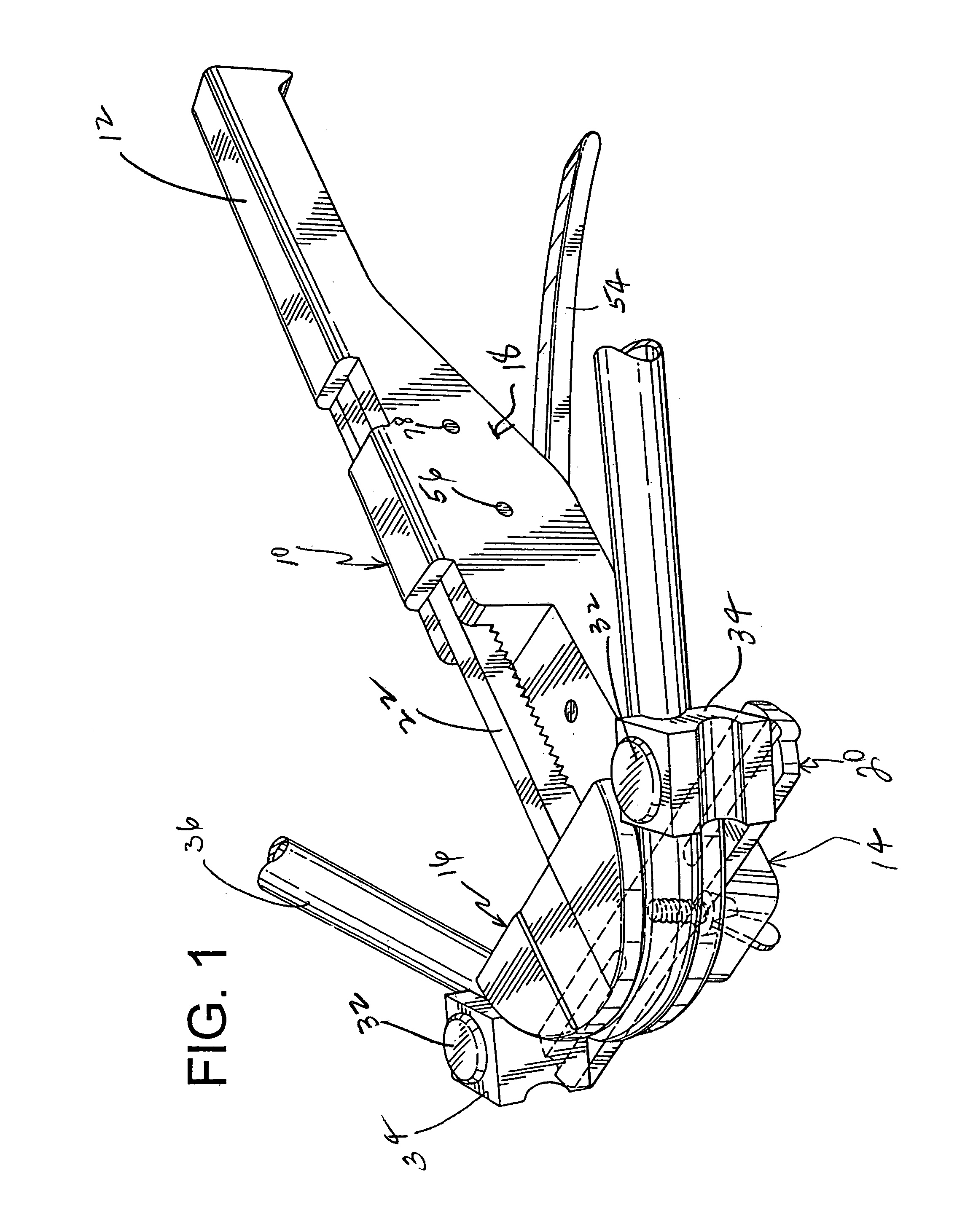
[0016]The tube-bending device of the invention is portable to be used by a person and is capable of bending metal tubes of copper, aluminum, or other metals. It serves to bend tubes of various diameters and can easily be moved from one worksite to another to accomplish the bending process.

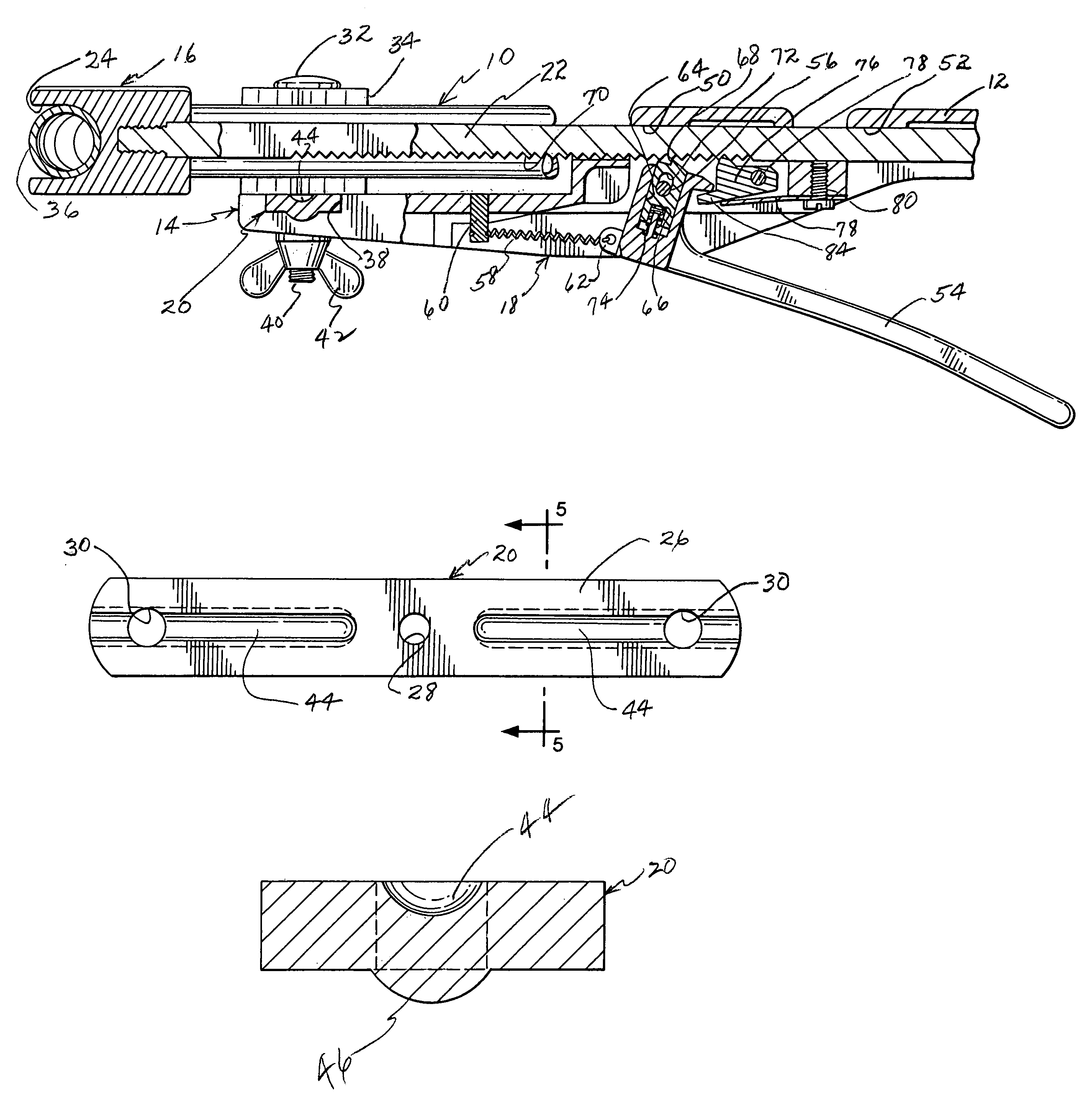
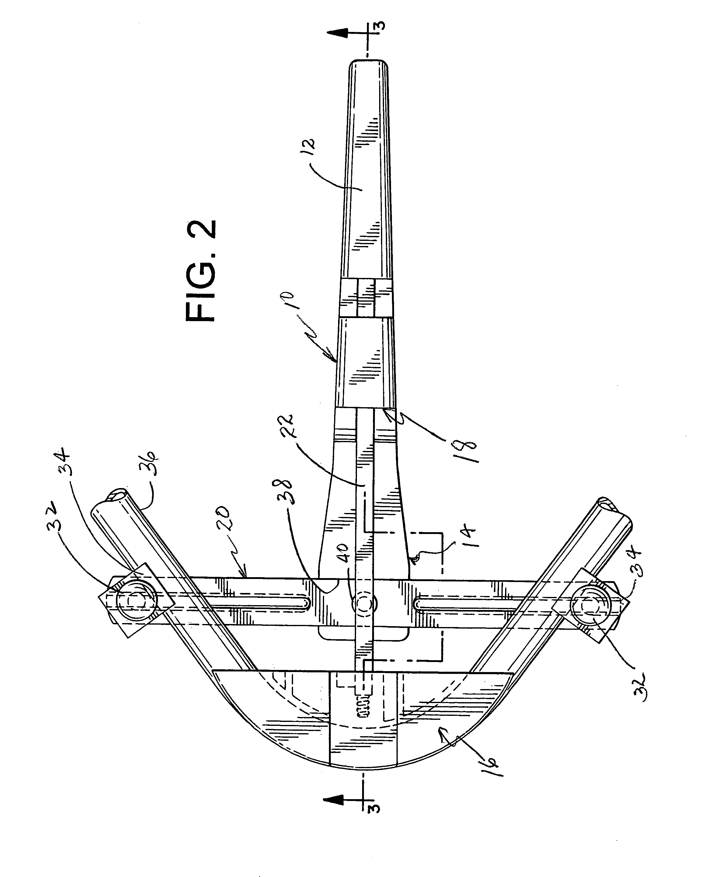
[0017]Referring now to the drawings, the tube-bending device includes generally a frame 10 having a handle 12 at one end and a tube-bending section 14 at the other end. An anvil 16 against which a tube may be placed is driven by a ratchet mechanism 18. Coacting with the anvil is a crossbar 20 mounted at the tube-bending section or end of the frame. As will be further described below, the crossbar is reinforced to enhance the life and operability of the tube-bending device according to the invention.

[0018]The anvil 16 is mounted on one end of a ratchet bar 22 of the ratchet mechanism 18, and the ratchet bar is reciprocably mounted in bar guides of the frame. The forward end of the ratchet bar 22 may...


PUM

PropertyMeasurementUnit
bendingaaaaaaaaaa
areaaaaaaaaaaa
diametersaaaaaaaaaa

Abstract

A tube-bending device including a frame having a reciprocably mounted anvil and a coacting crossbar with tube-restraining blocks, together with a ratchet mechanism for driving the anvil toward the blocks to perform tube-bending operations, wherein the crossbar is reinforced with reinforcing ribs to prevent failure.

Description

[0001]This invention relates in general to a tube-bending device for bending tubes, and more particularly to a tube-bending device having a strengthened crossbar to eliminate failure of the crossbar during tube-bending operations.BACKGROUND OF THE INVENTION[0002]Heretofore, it has been well known to provide tube-bending devices for bending of tube or pipe at a jobsite during construction of facilities using tubes or pipes, such as in plumbing or electrical work.[0003]A tube-bending device similar to the present invention is disclosed in U.S. Pat. No. 4,989,441, which includes an anvil driven by a ratchet mechanism and a crossbar coacting with the anvil for restraining tube or pipe elements during a tube-bending operation. A tube-bending device like that shown in the patent has been commercially produced and marketed for many years.[0004]It has been found that a tube-bending device like the patent experiences crossbar failure which results in the inability of the device to be used an...

Claims


Application Information

Patent Timeline
Patent Type & Authority Patents(United States)
IPC IPC(8): B21D7/00B21D7/04
CPCB21D7/04
Inventor MITSON, KEN J.
Owner MITSON KEN J
Why Eureka
Try Eureka