Manual hydrofoil and spar truss assembly for wind powered watercraft

a technology of hydrofoil and spar truss, which is applied in the direction of foil removal, special-purpose vessels, vessel construction, etc., can solve the problems of sailboat swamping or downflood, affecting the performance of sailboats, so as to increase the performance of small boats and reduce drag. , the effect of simple and efficient means

Inactive Publication Date: 2005-08-23
SLATTEBO JOHN
View PDF24 Cites 1 Cited by
  • Summary
  • Abstract
  • Description
  • Claims
  • Application Information

AI Technical Summary

Benefits of technology

[0016]The invention is a simple, lightweight, single moving part, manually-operated means of stabilizing and increasing the performance of small, lightweight, wind powered or sail-assisted paddling canoes and / or kayaks and small sailboats. It consists of a hydrofoil in the shape of the letter “L,” connected to a straight tubular shaft intended to fix the position of the hydrofoil to one side of the longitudinal axis of the hull of the canoe or kayak or sailboat (hereinafter “watercraft”), such that rotation of the tubular shaft around its long axis will both a) adjust the angle of attack of the hydrofoil when it is submerged and b) allow it to be rotated so that it is completely clear of the water when it is not needed to stabilize the watercraft. An adjustable length handle is affixed to the tubular shaft at a right angle thereto at the end opposite that to which the hydrofoil is affixed. This handle provides a simple and efficient means for the operator of the watercraft to make continuous manual adjustments to the hydrofoil's angle of attack while the watercraft is being sailed.
[0017]The tubular shaft portion of the invention is positioned below, slightly abaft, and parallel to the leading or forward most of two curved spars (known as “iakos” on Hawaiian paddling canoes). These two spars (hereinafter “iakos”) serve to position a small outrigger hull or floatation chamber (known as an “ama” on Hawaiian paddling canoes and hereinafter referred to as “ama”) to one side of, and parallel to, the hull of the watercraft. The ama provides stability to the narrow main hull of the watercraft when it is not making way through the water. When the watercraft is making way through the water under sail propulsion, the ama is elevated slightly (reducing drag), or is raised out of the water, as a result of lift created by the hydrofoil.

Problems solved by technology

Those monohull sailboats with a deep and heavy ballast keel typically will heel until deck edge immersion occurs, at with time drag increases dramatically and performance erodes.
In some cases, the sailboat may swamp or downflood.
Those monohull sailboats without a deep and heavy ballast keel typically will swamp or capsize.
For multihull sailboats, this heeling moment causes the windward hull to rise up relative to the leeward hull and will eventually result in the boat capsizing or “turning turtle.”
Patented devices intended to counteract heeling moment using hydrofoil technology are typically complicated mechanical devices involving many moving parts.
None of these existing devices has been successfully applied to address the problem of stabilizing small, lightweight paddling kayaks or canoes such that they can be operated both as high performance, human-powered watercraft and as high performance, wind-powered watercraft.
This is because they lack the simplicity of design and construction, the lightness in weight, and the ease of assembly and disassembly required to make them practical and appealing to the owner of the sort of canoe, kayak, or small sailboat that can be transported on the top of a car or other vehicle.
The demand for such a device, and the lack of applicability of existing patented devices, is apparent from the many advertisements contained in magazine for kayakers.
This device would not be adaptable for use with a small, “car-toppable” canoe, kayak, or sailboat.
The overall result is a complex system of parts unsuitable for weight, complexity, and cost to the problem of stabilizing a car-toppable canoe, kayak, or small sailboat.
The Hydrofoil Sailboat with Control Tiller in U.S. Pat. No. 4,228,750 to Smith, Oct. 21, 1980, is also extremely complex and ill-suited to the problem of stabilizing a car-toppable canoe, kayak, or sailboat.
It is not suitable for stabilizing a car-toppable canoe, kayak, or small sailboat.
It is not suitable for stabilizing car-toppable canoe, kayak, or small sailboat.
Without the truss arrangement, i.e., if the iako and the foil-controlling tubular shaft are combined as a single tube or shaft, or as concentric tubes or shafts, then the tendency of the shaft or shafts to flex or distort will interfere with foil control and will cause the foil's angle of attack, as well as its vertical and horizontal lift vectors, to change in accordance with the amount of flexion or distortion.

Method used


Image

  • Manual hydrofoil and spar truss assembly for wind powered watercraft
  • Manual hydrofoil and spar truss assembly for wind powered watercraft
  • Manual hydrofoil and spar truss assembly for wind powered watercraft

Examples


Embodiment Construction

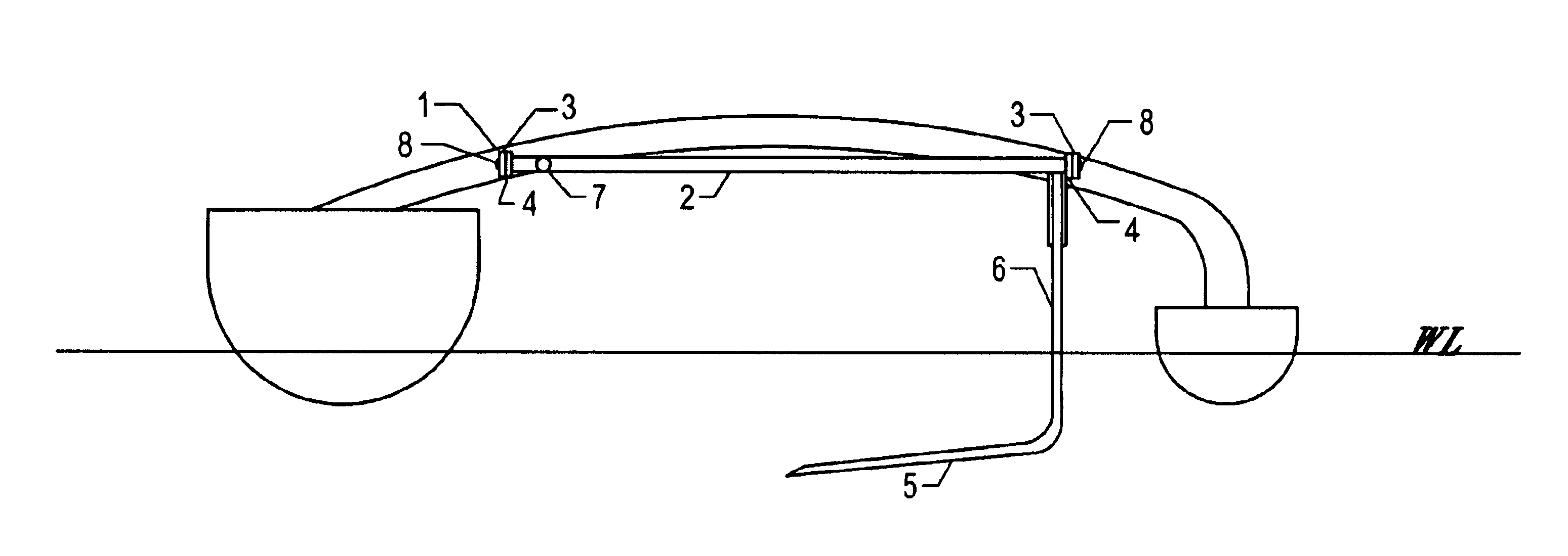
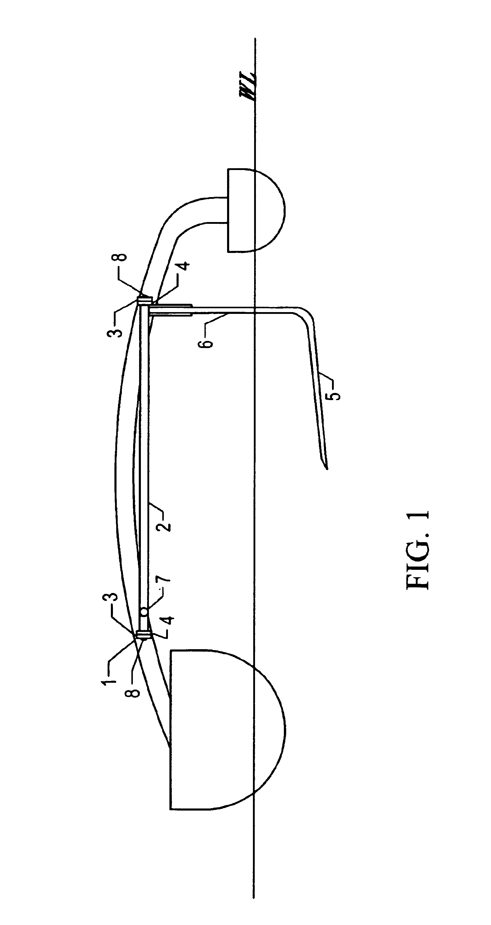
[0045]FIG. 1 is a view of the truss assembly from aft or astern of the watercraft showing the assembly's relationship to the main hull and the ama. The vertical relationship between the iako (1) and the tubular shaft (2) is apparent from this view. The position of the tubular shaft (2) relative to the iako (1) is maintained by means of short struts (3) that are welded or otherwise fixed to the iako (1) at their upper ends and that are attached to the tubular shaft at their lower ends either by means of two machine screws (8) that pass through holes in the struts and fasten into the ends of the tubular shaft, or by means of a sleeve (4) within which the tubular shaft can rotate. The tubular shaft (2) can rotate around its long axis within this sleeve (4), with the machine screws (8) rotating in holes bored in the struts (3). This rotation causes the angle of attack of the submerged blade portion (5) of the “L” foil to change, thereby creating a downward or upward force to be exerted ...


PUM


Abstract

A simple, lightweight, manually-controlled device for stabilizing and increasing the performance of small, sail-assisted watercraft, containing a single moving part and comprising a curved spar or iako (1) joining a main hull and a single outrigger hull or ama, a tubular shaft (2) with a handle (7) at one end and an “L” shaped hydrofoil (5 and 6) at the other end. The tubular shaft (2) is joined to the iako (1) by two or more struts (3) that are fixed to the iako (1) at their upper ends and have machine screws (8) or sleeves (4) at their lower ends by means of which the tubular shaft (2) is permitted to rotate around its longitudinal axis and is prevented from moving horizontally in relation to the curved iako (1), thereby making the entire assembly a truss or girder that resists vertical distortion or flexion. The vertical portion of the foil (6) makes an obtuse angle of specified range with the submerged blade portion of the foil (5) so that a horizontal force vector in a windward direction is created by the foil when it moves through the water, regardless of the tack on which the watercraft is sailed. An accessory device for transporting either a single passenger or equipment, consisting of two fore-and-aft rails (9) the ends of which rest on, or snap onto, or are otherwise affixed to the iako (1) and a second iako abaft thereof, and a webbing or fabric sling (10) attached to and suspended between said fore-and-aft rails (9).

Description

CROSS-REFERENCE TO RELATED APPLICATIONS[0001]This application is entitled to the benefit of Provisional Patent Application Ser. No. 60 / 393,622, filed Jul. 3, 2002.BACKGROUND[0002]1. Field of the Invention[0003]This invention relates to wind powered or sail assisted watercraft and more particularly those watercraft using a single submerged hydrofoil for stabilization and improved performance.[0004]2. Description of Prior Art[0005]A number of patents have been granted covering hydrofoil devices intended to counteract the heeling moment imparted by wind pressure on the sails and masts of small sailing craft or saiboats. For monohull saiboats, this heeling moment causes the boat to heel or roll around the longitudinal axis of the hull. Those monohull sailboats with a deep and heavy ballast keel typically will heel until deck edge immersion occurs, at with time drag increases dramatically and performance erodes. In some cases, the sailboat may swamp or downflood. (Capsizing is rare, exce...

Claims


Application Information

Patent Timeline
Patent Type & Authority Patents(United States)
IPC IPC(8): B63B39/00B63B1/16B63B1/28B63B1/00B63B39/06B63B1/12B63B1/24B63B41/00
CPCB63B1/121B63B1/242B63B1/285B63B39/062B63B41/00B63B2001/102B63B34/45
Inventor SLATTEBO, JOHN
Owner SLATTEBO JOHN
Why Eureka
Try Eureka