Diamond core drill bit

a diamond core and drill bit technology, applied in the field of diamond core drill bits, can solve the problems of not teaching or enabling diamond grit in substantially simpler bit construction, extensive prior art in this field, and reducing the waste of cut materials, so as to achieve the effect of minimizing waste, simple and efficient means, and optimizing drilling efficiency

Active Publication Date: 2007-04-17
LUMINARE SUPPLY CORP
View PDF20 Cites 18 Cited by
  • Summary
  • Abstract
  • Description
  • Claims
  • Application Information

AI Technical Summary

Benefits of technology

[0005]The present invention incorporates a unique combination of features that provide optimal drilling efficiency in both natural and man made materials. The invention incorporates simple and efficient means for (1) minimizing waste in the cut material with an overall bit design that enables the use of a thin-walled drill bit; (2) improving diamond quantity and bond strength on the bit's cutting edge to lengthen the life of the bit; (3) lubricating the cutting surface from the inside of the bit using center lubricant feed system to improve the cut; (4) removing cutting debris from the inside of the bit to reduce cutting time and heat generation; (5) obtaining a smooth bore in the drilled material to improve quality; and (6) removing the core from the drill bit when the cut is finished to reduce time to completion.

Problems solved by technology

The prior art in this field is extensive, but does not teach grooved sidewall bonding.
It does not teach or enable diamond grit in substantially simpler bit construction.
However, these lack the efficiency improvements of the present invention.
However, such simplistic prior art does not disclose axial grooves on the sidewall surface of the drill extending to the cutting edge to improve diamond bonding, lubrication efficiency and drill bit lifetime.

Method used


Image

  • Diamond core drill bit
  • Diamond core drill bit
  • Diamond core drill bit

Examples


Embodiment Construction

[0019]The preferred embodiment of the diamond core drill bit is shown in the figures and is described herein. This detailed description focuses on the preferred embodiment. While some alternative embodiments are noted herein, the detailed description is not intended to limit the invention, which is defined by the claims.

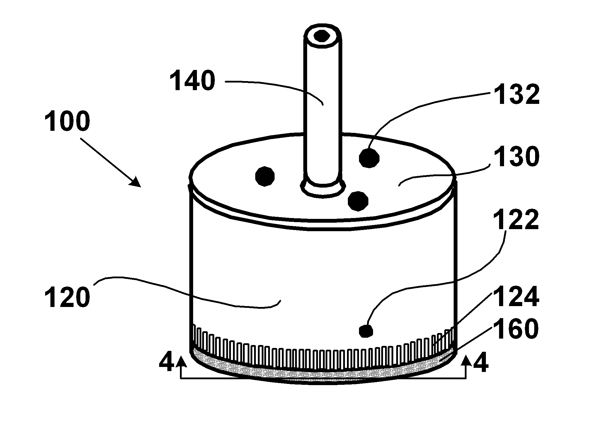
[0020]FIG. 1 shows a perspective of the diamond core drill bit (100). The drill bit (100) could be made in any size desired for drilling, but in the preferred embodiment would have a drilling diameter of about 3 inches or less and an overall height of about 3 inches or less. The drill bit need not be coated, but preferably would have a nickel plating to inhibit rust, to reduce friction, and to present a clean, shiny, and silvery appearance.

[0021]The drill bit (100) has a body (120) that is in the form of a right-circular cylinder. The body (120) is typically made of steel, but any sturdy material commonly used for such bits, such as titanium, aluminum, copper, brass,...


PUM

PropertyMeasurementUnit
drilling diameteraaaaaaaaaa
heightaaaaaaaaaa
diameteraaaaaaaaaa

Abstract

A diamond core drill bit (100) is disclosed. The drill bit has a right-circular cylindrical body (120) with at least one side lubrication hole (122) toward the bottom of the body and a plurality of parallel grooves (124) oriented in an axial direction at the bottom circumferential sidewall of the body. A cap (130) at the top of the cylindrical body (120) closes one end of the body. The cap has a central lubrication hole (134) and alternative embodiments have at least one core extraction hole (132). These holes extend through the cap to the interior of the body. A hollow drive shaft (140) is mated to the cap (130) over the central lubrication hole (134), such that a lubricant can flow through the hollow shaft and into the internal volume of the body and out a side lubrication hole (122). Diamond grit (160) is bonded around the bottom edge on a portion of the internal and external sidewall surfaces at the bottom circumferential edge of the body (120) in such a way that the diamond grit (160) is bonded over a portion of the axial height of the grooves (124).

Description

FIELD OF INVENTION[0001]In the field of tools for penetrating hard materials, such as tile, stone, glass, ceramics and porcelain, the invention relates to a rotatable diamond drill bit having a core-receiving central portion.BACKGROUND OF THE INVENTION[0002]Very hard materials such as glass, stone, tile, ceramic and porcelain, generally cannot be drilled with standard steel or carbide bits because of the extreme hardness of the material. One solution is to bond diamonds (or other extremely hard materials) onto the tip of a specially designed drill bit, allowing the diamonds to perform the actual cutting process. Diamonds are extremely hard and provide a durable cutting edge.[0003]Several drawbacks are attendant to the use of diamonds on drill bits. The more diamonds that are bonded to the cutting edge, the longer the life of the bit. However, additional diamond layers have less bond strength and result in a thicker cut in the work piece. In addition, during use, two primary forces a...

Claims


Application Information

Patent Timeline
Patent Type & Authority Patents(United States)
IPC IPC(8): B28D1/14
CPCB28D1/041
Inventor PEDERSEN, LYLE DEAN
Owner LUMINARE SUPPLY CORP
Why Eureka
Try Eureka