
Shock absorbing device

a technology of shock absorption device and shock absorber, which is applied in the direction of shock absorbers, elastic dampers, cycle equipment, etc., can solve problems such as difficult deformation, and achieve the effect of sufficient shock absorption

Inactive Publication Date: 2005-08-23
HONDA MOTOR CO LTD
View PDF17 Cites 28 Cited by
  • Summary
  • Abstract
  • Description
  • Claims
  • Application Information

AI Technical Summary

Benefits of technology

[0008]It is an object of the present invention to solve the above-mentioned problems and to provide a shock absorbing device capable of producing a sufficient shock absorbing effect by causing an expected deformation of a shock absorbing member under the shock upon collision.
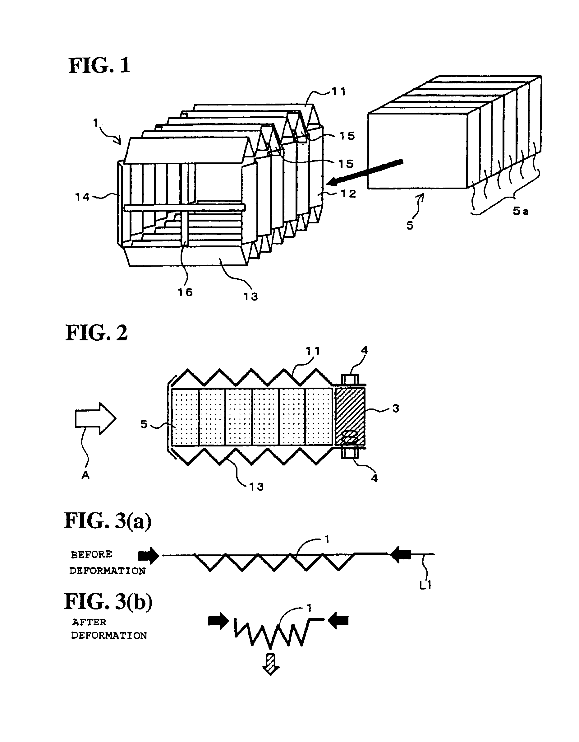
[0014]According to the present invention, when the external force is exerted on the shock absorbing device, the cover is easy to be deformed in the compression direction but is not easy to be deformed in the directions orthogonal to the compression direction, so that the shock absorbing material can receive a compressive force corresponding to the external force in the state of being restrained from deformation in the directions orthogonal to the external force. As a result, the shock energy can be absorbed sufficiently.
[0016]According to the present invention, with the bellows structure body easily deformable in one direction, it is possible to provide a cover which can be easily deformed in the compression direction under the external force and can be restrained from deformation in directions orthogonal to the compression direction.
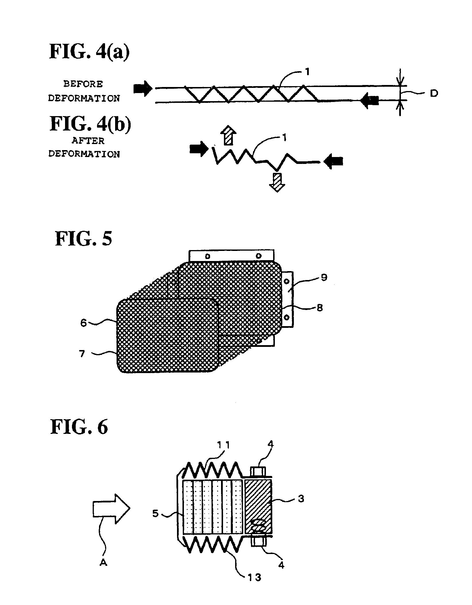
[0017]According to the present invention, since the mesh is easily deformable and, simultaneously, is inhibited from deformation by the frames, it is possible to provide a cover which can be easily deformed in the compression direction under the external force and can be restrained from deformation in directions orthogonal to the compression direction.

Problems solved by technology

The cover has a structure such that it is easy to be deformed in the compression direction of the shock absorbing material under an external force and is difficult to be deformed in directions orthogonal to the compression direction.

Method used


Image

  • Shock absorbing device
  • Shock absorbing device
  • Shock absorbing device

Examples


Embodiment Construction

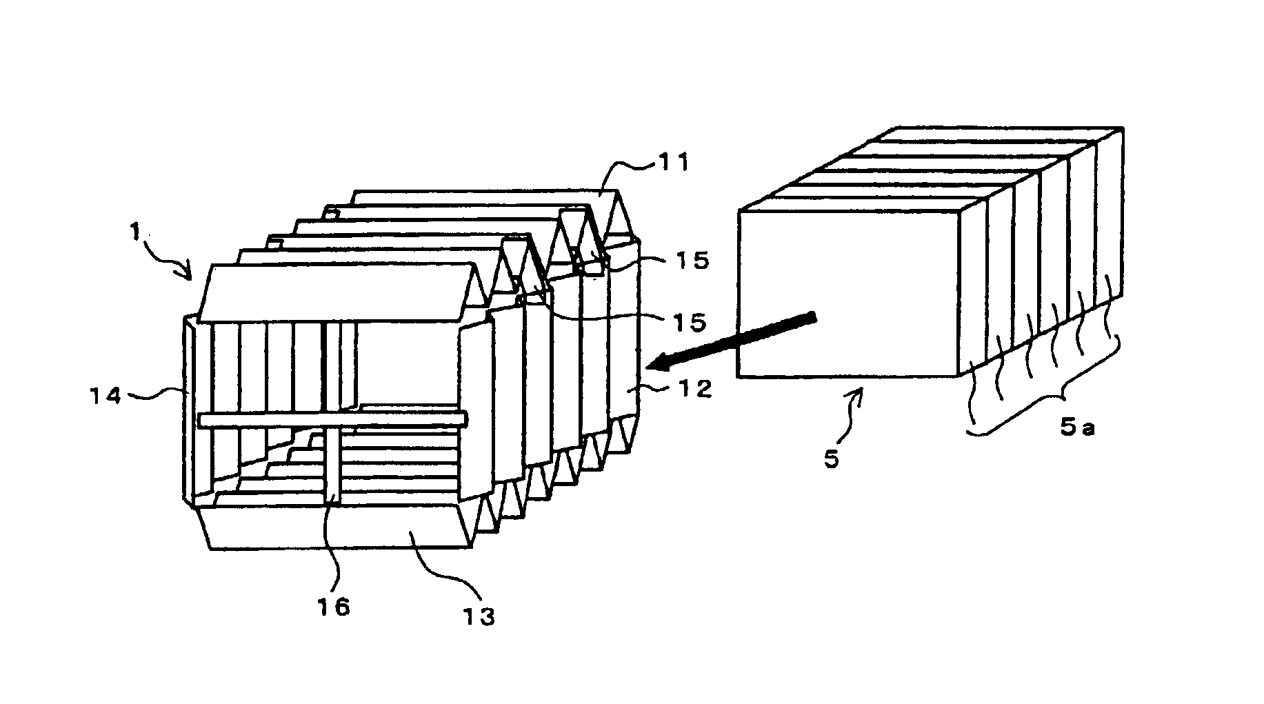
[0027]The present invention will be described in detail below referring to the drawings. FIG. 1 is a perspective view of a cover included in a shock absorbing device according to one embodiment of the present invention. In FIG. 1, the cover 1 is in a roughly rectangular parallelopiped box shape, and is surrounded by four surfaces, i.e., upper, lower, left and right corrugated plates 11, 12, 13 and 14. Clamp plates 15 for connection of intersecting corner portions of the corrugated plates 11 to 14 and cross bars 16 for coupling end portions of the corrugated plates 11 to 14 are attached to the cover 1. Incidentally, while only the clamp plates 15 are provided at one corner, of the four corners, as shown in FIG. 1, it is preferable to provide at least two clamp plates at each of the four corners.

[0028]While the corrugated plates 11 to 14 are desirably corrugated sheets of aluminum or an aluminum alloy, it is possible to appropriately select a sheet of other metal, a molded resin plate...


PUM


Abstract

To prevent a shock absorbing material mounted on a vehicle body from collapsing or being scattered under the shock at the time of a collision. The four sides of a shock absorbing material formed of a foamed material are surrounded by a bellows form cover consisting of four corrugated plates inclusive of corrugated plates. Under an external force due to collision, the bellows is folded and contracted easily, but is difficult to be deformed in the width directions. Therefore, the shock absorbing material receives the energy upon collision in its initial shape, so that the energy is absorbed substantially by the compression of the shock absorbing material. Accordingly, it suffices to design a set load for the shock absorbing material by taking into account only the shock absorbing material, so that it is easy to design the shape, material and the like of the shock absorbing material.

Description

BACKGROUND OF THE INVENTIONCROSS-REFERENCE TO RELATED APPLICATIONS[0001]The present nonprovisional application claims priority under 35 USC 119 to Japanese Patent Application No.2002-189794 filed on Jun. 28, 2002 the entire contents thereof is hereby incorporated by reference.[0002]1. Field of the Invention[0003]The present invention relates to a shock absorbing device, and particularly to a shock absorbing device which is mounted on a vehicle such as a motorcycle and which can protect the rider(s) and equipment and materials at the time of collision.[0004]2. Description of Background Art[0005]In order to alleviate a shock exerted on the rider(s) upon collision of a vehicle or to mitigate the damage to the vehicle main body upon the collision, a shock absorbing device is provided. For example, Japanese Patent No. 3207789 discloses a deformation element as a shock absorbing device which is supported on a vehicle body frame of a motorcycle which projects to the front side of the vehic...

Claims


Application Information

Patent Timeline
Patent Type & Authority Patents(United States)
IPC IPC(8): B62J27/00B60R19/22B60R19/18F16F7/12F16F1/37F16F7/00
CPCB60R19/22B62J27/00F16F1/37F16F7/003F16F7/121F16F7/123B62J27/30
Inventor AKIYAMA, HIDEKIKURATA, NORIHIRO
Owner HONDA MOTOR CO LTD
Learn More