Windback labyrinth seal that accommodates a pressure differential for rotating shafts

a technology of labyrinth seal and rotating shaft, which is applied in the direction of engine seals, leakage prevention, machines/engines, etc., can solve the problems that the labyrinth seal cannot maintain a significant pressure drop between the interior and exterior of the bearing housing, and contravene their very purpose, so as to prevent oil leakage, prevent pressure drop, and prevent oil leakage

Inactive Publication Date: 2005-08-23
HYUNDAI IDEAL ELECTRIC
View PDF11 Cites 26 Cited by
  • Summary
  • Abstract
  • Description
  • Claims
  • Application Information

AI Technical Summary

Benefits of technology

[0006]In accordance with another aspect of the invention, the segmented labyrinth seal has a windback configuration formed around a rotatable shaft for preventing leakage of oil from a bearing housing. The seal includes a first face and a second face with an exterior cylindrical surface and an interior cylindrical surface extending between the first face and the second face. A thread pattern is provided on the interior cylindrical surface selectively configured in a right-hand direction and a left-hand direction, the thread pattern providing the windback configuration. The thread pattern is formed by a plurality of profiled teeth having first sides, second sides, and connecting sides extending between the first sides and the second sides. The plurality of profiled teeth have a vertical tooth height, and leading edges are formed where the first sides join the connecting sides and trailing edges are formed where the second sides join the connecting sides. The first sides and the second sides are slanted toward the first face, and a pressure drop is taken over the plurality of profiled teeth. The pressure drop is from a higher pressure near the second face to a lower pressure near the first face. A channel which traces the thread pattern is formed between the first sides and the second sides of adjacent teeth of the plurality of profiled teeth. The channel is adapted for capturing the oil from the bearing housing, and returning the oil to the bearing housing without the need for axial drain holes. The labyrinth seal is adapted to accommodate the aforementioned pressure drop, and the vertical tooth height of the plurality of profiled teeth prevents the pressure drop from having adverse effects on the performance of the seal.
[0007]In accordance with yet another aspect of the invention, the segmented labyrinth seal has a windback configuration formed around a rotatable shaft for preventing leakage of oil from a bearing housing. The seal includes two half-circle shaped segments having first and second ends. When assembled, the two half-circle shaped segments form a cylindrical shape, and the first ends abut one another and the second ends abut one another. The seal also includes an exterior cylindrical surface and an interior cylindrical surface, and the exterior cylindrical surface and the interior cylindrical surface extend between a first face and a second face. A thread pattern is provided on the interior cylindrical surface, and the thread pattern is selectively configured in a right-hand direction when the rotatable shaft is rotating clockwise when looking down the rotatable shaft toward the bearing housing and in a left-hand direction when the rotatable shaft is rotating counter-clockwise when looking down the rotatable shaft toward the bearing housing. First and second split-line pins are respectively located on the first and second ends of one of the two half-circle shaped segments, and first and second holes are respectively provided on the first and second ends of the other of the two half-circle shaped segments. The first hole receives the first split-line pin and the second hole receives the second split-line pin when the segmented labyrinth seal is assembled. The position of the first hole and the first split-line pin is staggered in relation to the second hole and the second split-line pin depending on the selective configuration of the thread pattern in the right-hand direction and the left-hand direction. The thread pattern is formed by a plurality of profiled teeth having first sides, second sides, and connecting sides extending between the first sides and the second sides. The plurality of profiled teeth have a vertical tooth height, and leading edges are formed where the first sides join the connecting sides and trailing edges are formed where the second sides join the connecting sides. The first sides and the second sides respectively form first and second angles that are oblique with respect to the interior cylindrical surface, the first angle always being greater than the second angle. A pressure drop is taken over the plurality of profiled teeth, and is divided into various intermediate pressures between adjacent teeth of the plurality of profiled teeth. A channel which traces the thread pattern is wound in a direction opposite to the rotational direction of the rotatable shaft. The channel is adapted for capturing the oil from the bearing housing, and returning the oil to the bearing housing without the need for axial drain holes. The vertical tooth height of the plurality of profiled teeth is chosen to allow for a primary flow of said oil directed to the bearing housing in the channel, and to prevent secondary flow of the oil in an opposite direction to the primary flow in the channel.

Problems solved by technology

However, the use of axial drain holes has two limitations.
Because the terminal tooth cannot withstand a significant pressure drop, these labyrinth seals cannot maintain a significant pressure drop between the interior and exterior of the bearing housing.
Second, the axial drain holes actually siphon oil from the bearing housing into the channels formed between the individual teeth.
Consequently, the axial drain holes actually interfere with the efficient return of the oil to the bearing housings, and contravene their very purpose.

Method used


Image

  • Windback labyrinth seal that accommodates a pressure differential for rotating shafts
  • Windback labyrinth seal that accommodates a pressure differential for rotating shafts
  • Windback labyrinth seal that accommodates a pressure differential for rotating shafts

Examples


Embodiment Construction

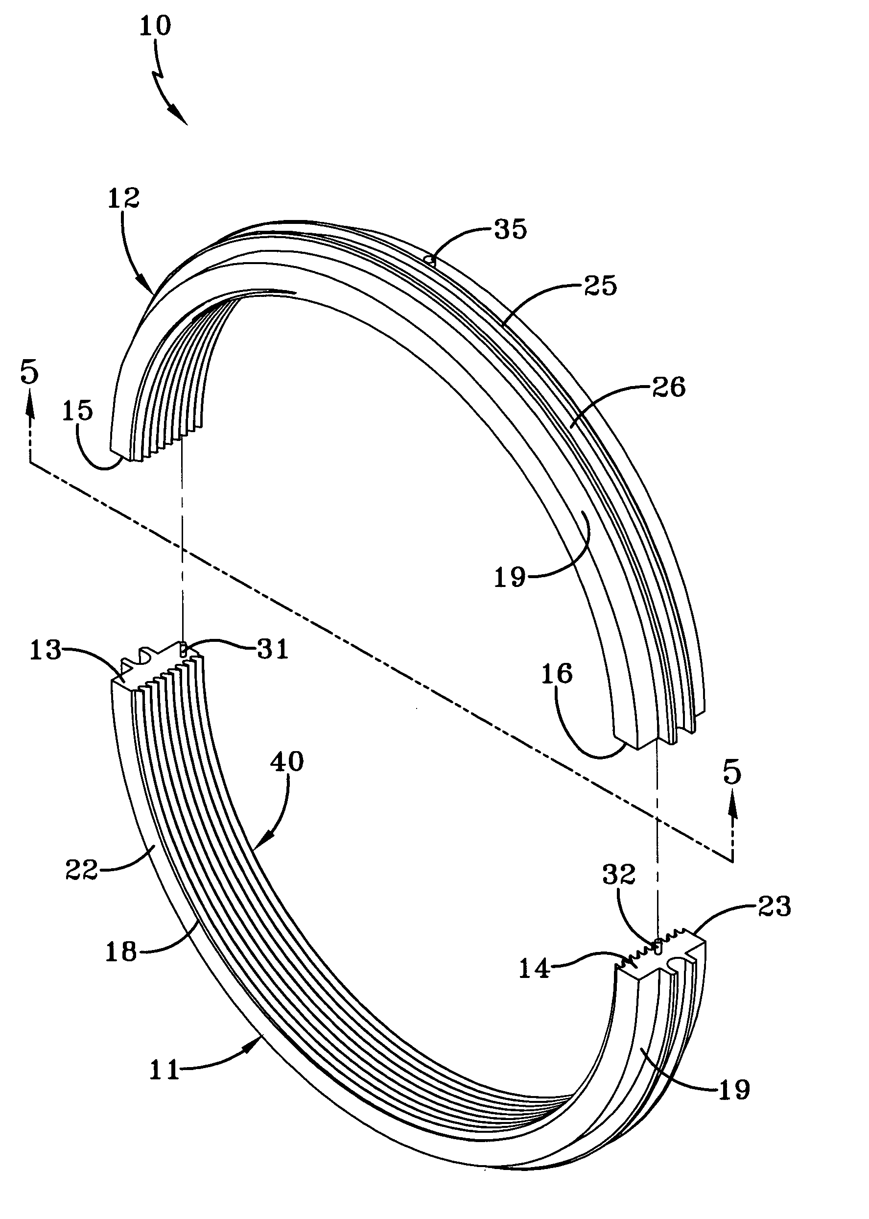
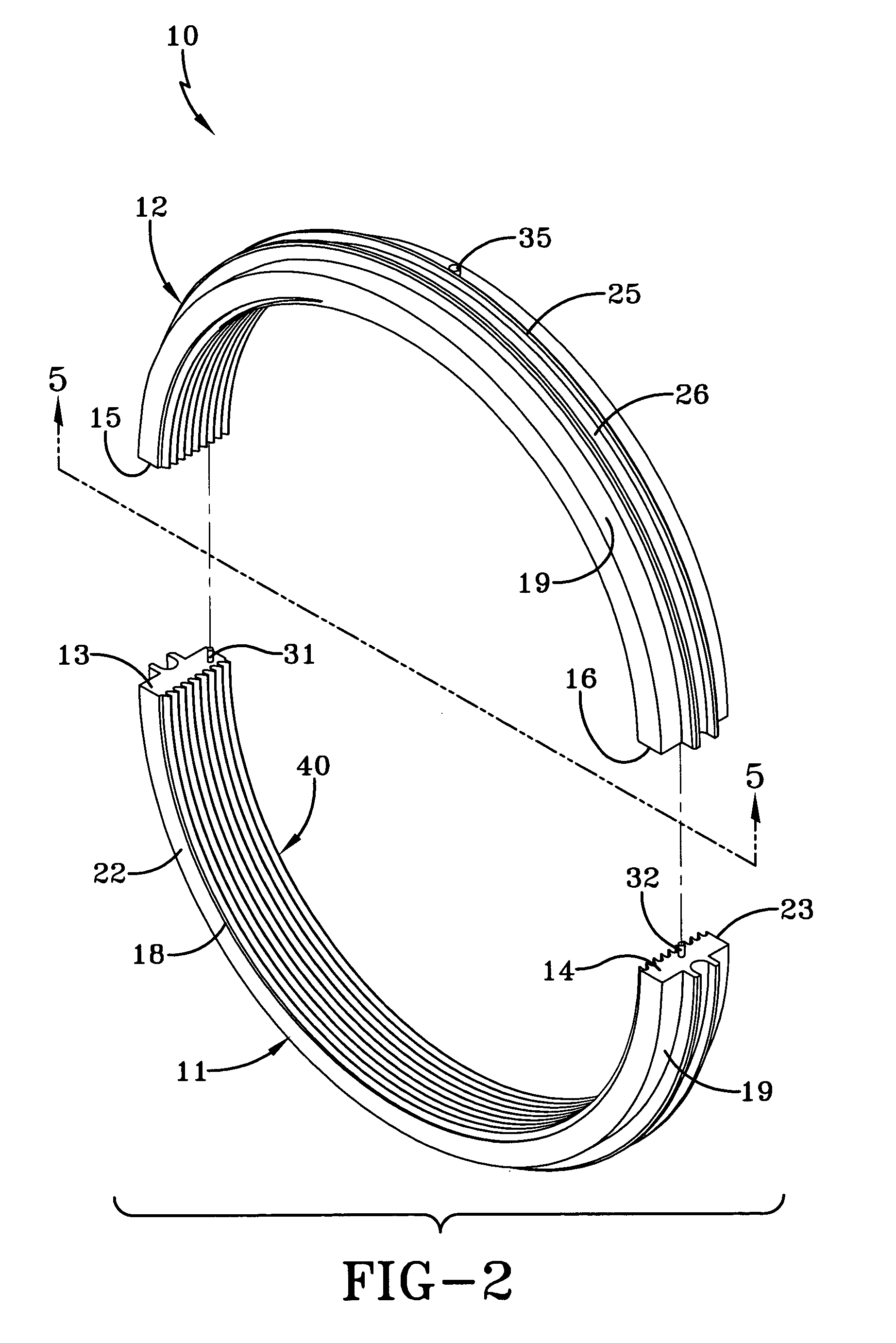
[0018]Referring first to FIG. 1, the segmented labyrinth seal of the present invention is generally indicated by the numeral 10. The segmented labyrinth seal 10 can be constructed of Xiton, or other similar material and is made up of first and second half circle-shaped segments 11 and 12. As seen in FIG. 2, the first segment 11 has first and second ends 13 and 14, respectively, and the second segment 12 has first and second ends 15 and 16, respectively. First ends 13 and 15 abut one another, and the second ends 14 and 16 abut one another when the segmented labyrinth seal 10 is assembled along a split-line 17 as best seen in FIGS. 3 and 4. The split-line 17 delineates the portions of the segmented labyrinth seal 10 housed in the first half and second half of a bearing housing (not shown). As such, the first segment 11 will be housed (or encapsulated) in the first half of the bearing housing and the second segment 12 will be housed in the second half of the bearing housing.

[0019]When ...


PUM


Abstract

A segmented labyrinth seal (10) having a windback configuration formed around a rotatable shaft for preventing leakage of oil from a bearing housing having a first face (22) and a second face (23). An exterior cylindrical surface (19) and an interior cylindrical surface (18) extend between the first face (22) and the second face (23). A thread pattern (40) provided on the interior cylindrical surface (18) providing the windback configuration, and configured in a right-hand direction or a left-hand direction. A plurality of profiled teeth (41) form the thread pattern (40) and have first sides (43), second sides (44), and connecting sides (45) extending between the first sides (43) and the second sides (44). Leading edges (47) are formed where the first sides (43) join the connecting sides (45), and trailing edges (48) are formed where the second sides (44) join the connecting sides (45). The first sides (43) and the second sides (44) are slanted toward the first face (22). A pressure drop is taken over the plurality of profiled teeth (41). A channel (C) tracing the thread pattern (40) is formed between the first sides (43) and the second sides (44) of adjacent teeth of the plurality of profiled teeth (41), the channel being adapted to capture the oil from the bearing housing, and returning the oil to the bearing housing without the need for axial drain holes.

Description

TECHNICAL FIELD[0001]The present invention relates to a segmented labyrinth seal having a windback configuration.BACKGROUND ART[0002]Labyrinth seals are widely used to surround rotatable shafts, and prevent leakage of oil from bearing housings. Generally, either parallel or thread-like teeth patterns are formed on the interior surfaces of these labyrinth seals. The tips of each tooth of the parallel and thread-like teeth patterns provide a radial clearance with respect to the rotatable shaft, and the channels formed between the teeth of these teeth patterns are used to capture the oil. However, even when using a thread-like teeth pattern, axial drain holes have universally been used to return the oil to the bearing housings. These axial drain holes are parallel to the axis of the rotatable shaft, and are drilled through each tooth of the teeth pattern except for tooth farthest removed from the bearing housing, the so-called terminal tooth. As such, the axial drain holes join the cha...

Claims


Application Information

Patent Timeline
Patent Type & Authority Patents(United States)
IPC IPC(8): F16J15/447F16J15/44F16J15/40
CPCF16J15/406F16J15/44F16J15/4472
Inventor HUSTED, DALE E.
Owner HYUNDAI IDEAL ELECTRIC
Why Eureka
Try Eureka