
Image processing system, projector, program, information storage medium and image processing method

a technology of image processing and information storage medium, which is applied in the direction of printers, cameras, instruments, etc., can solve the problems of image distortion, image distortion, and image correction, and achieve the effect of achieving higher speed and projecting an image more accurately

Inactive Publication Date: 2005-08-23
SEIKO EPSON CORP
View PDF13 Cites 35 Cited by
  • Summary
  • Abstract
  • Description
  • Claims
  • Application Information

AI Technical Summary

Benefits of technology

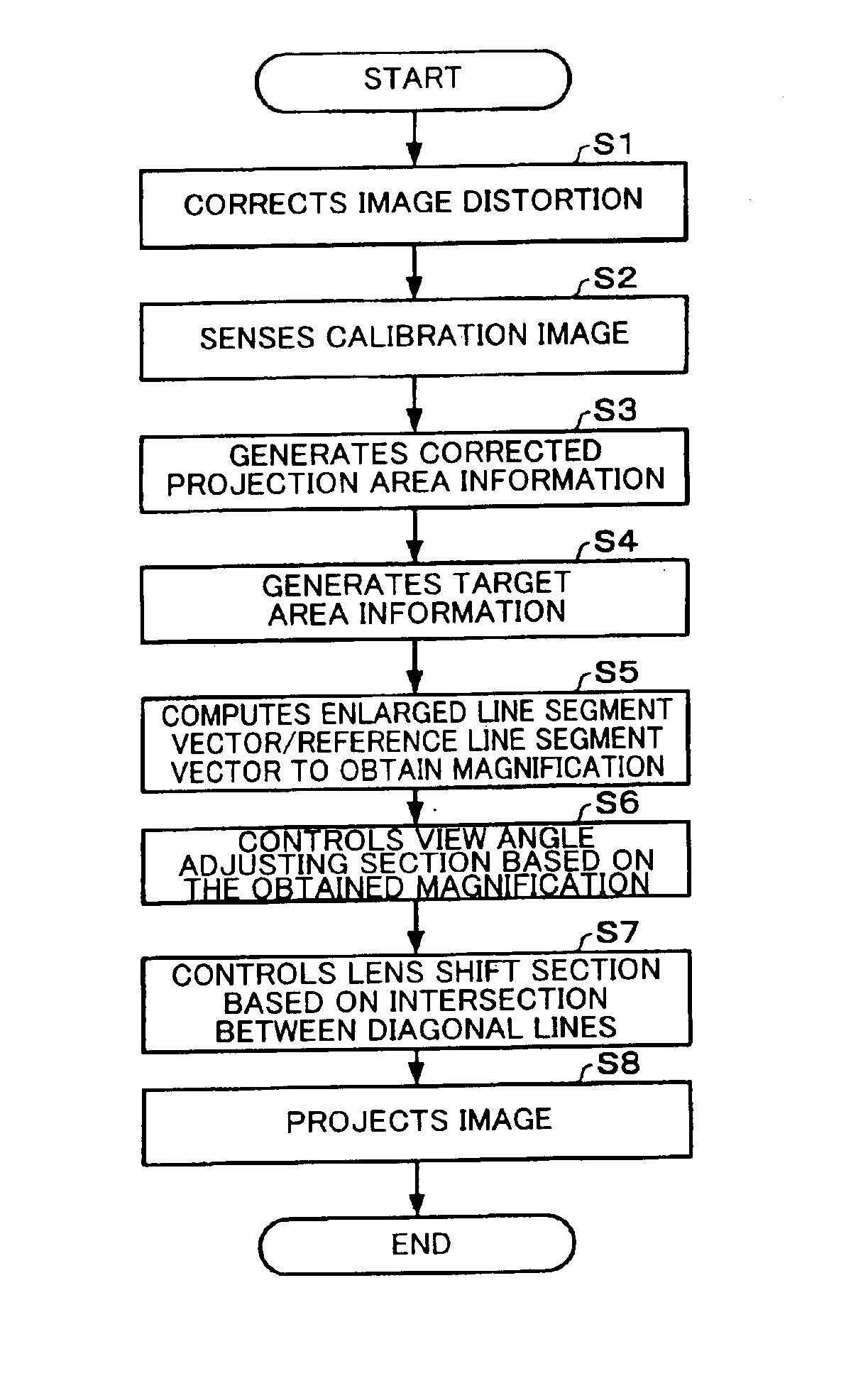
[0013]The present invention is made in view of the above-mentioned problems, and may provide an image processing system, projector, program, information storage medium and image processing method enabling to project an image more accurately at a higher speed while using a target area of a projection target such as a screen as effectively as possible.
[0060]Thus, the image processing system and others can project an image accurately and at higher speed while using the target area of the projection target such as a screen as effectively as possible.
[0061]Moreover, since the image processing system and others can perform image processing by using only one sensing section, they can project an image at higher speed than the case where a plurality of sensing sections are used.
[0100]Thus, the image processing system and others can project an image accurately and at higher speed while using the target area of the projection target such as a screen as effectively as possible.
[0101]Moreover, since the image processing system and others can perform image processing by using only one sensing section, they can project an image at higher speed than the case where a plurality of sensing sections are used.

Problems solved by technology

This is very troublesome for the user.
In addition, there is a case that an image is distorted to create a so-called keystone distortion in the vertical or horizontal direction depending on the relative angle between the optical axis of a light projected from an image projection device such as a projector and an object onto which the light is projected, such as a screen.
However, the general image projecting device having a distortion correcting function includes an inclination sensor which can only correct the distortion of an image in the vertical direction, but not in the horizontal direction.
It is troublesome for the user to indicate the four corner points on the screen through the mouse.
However, in such a technique of Japanese Patent Laid-Open No. 2000-241874 that the angle of view is adjusted by using the scaling function of the projection lens to enlarge or reduce the projected image until it reaches the end points of the sensed screen, the process takes much time.
Furthermore, the technique of Japanese Patent Laid-Open No. 2000-241874 cannot be applied to a case where the aspect ratio of the screen is different from that of the projected image.
Additionally, Japanese Patent Laid-Open No. 2000-241874 describes the adjustment of the image display position by adjusting the depression and elevation angles of the projection lens to display the projected image on the screen at its center, but does not concretely disclose how the process has been performed.

Method used


Image

  • Image processing system, projector, program, information storage medium and image processing method
  • Image processing system, projector, program, information storage medium and image processing method
  • Image processing system, projector, program, information storage medium and image processing method

Examples


Embodiment Construction

[0115]Embodiments of the present invention applied to a projector having an image distortion correcting function will be described with reference to the drawing. Note that the embodiments described below do not in any way limit the scope of the present invention defined by the claims laid out herein. Similarly, all the elements of the embodiments below should not be taken as essential requirements defined by the claims herein.

Entire System

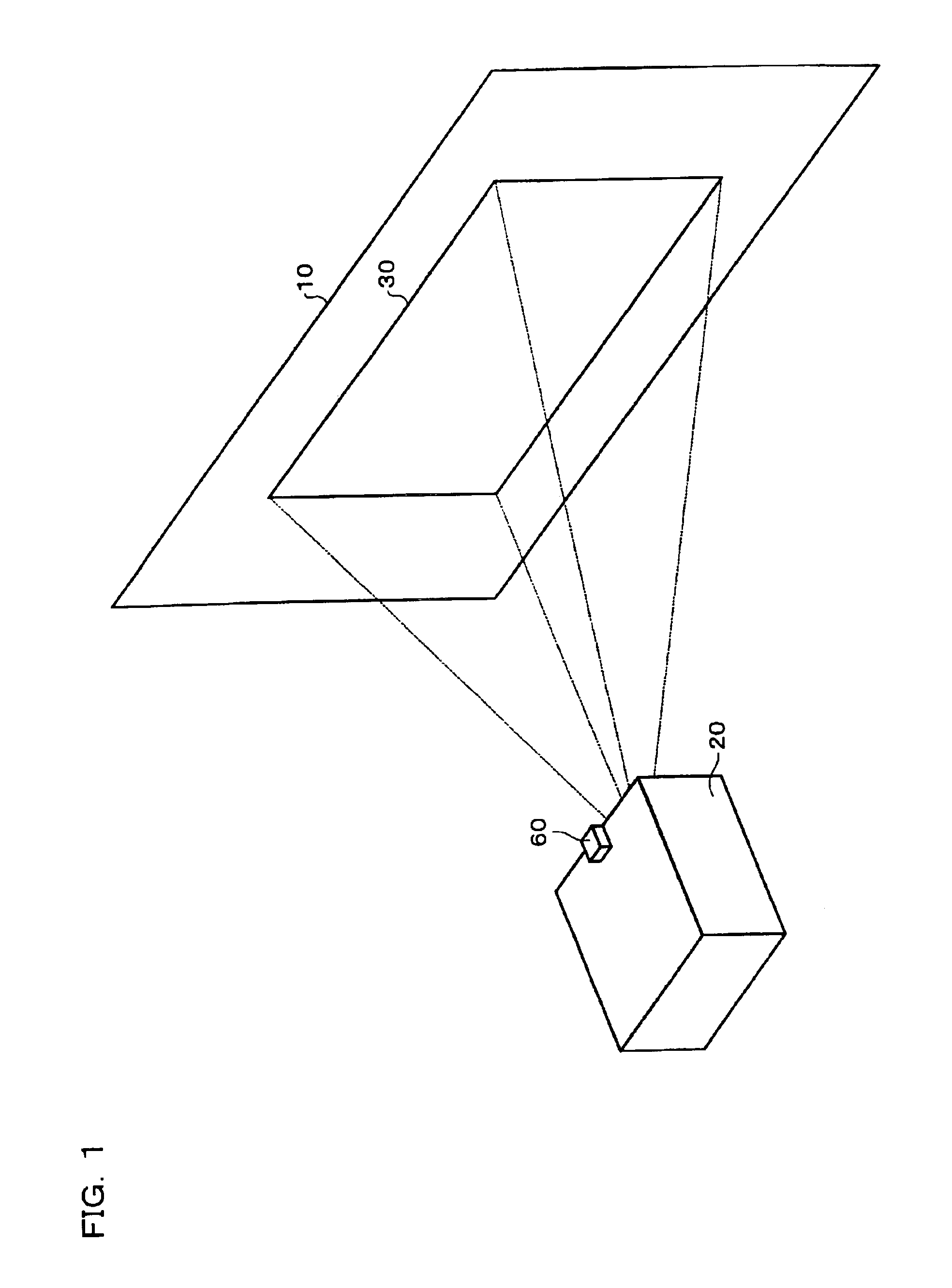
[0116]FIG. 1 is a diagram showing image projection.

[0117]A projector 20, which is a kind of image processing system, projects an image onto a screen 10 which is a kind of projection target having a rectangular target area. Thus, a projected image 30 is displayed on the screen 10.

[0118]In this embodiment, the projector 20 is not positioned directly in front of the screen 10. For such a reason, the projected image 30 has a distortion (e.g., a so-called keystone distortion).

[0119]In this embodiment, a sensor 60, which is part of image pickup means, is...


PUM

PropertyMeasurementUnit
aspect ratioaaaaaaaaaa

Abstract

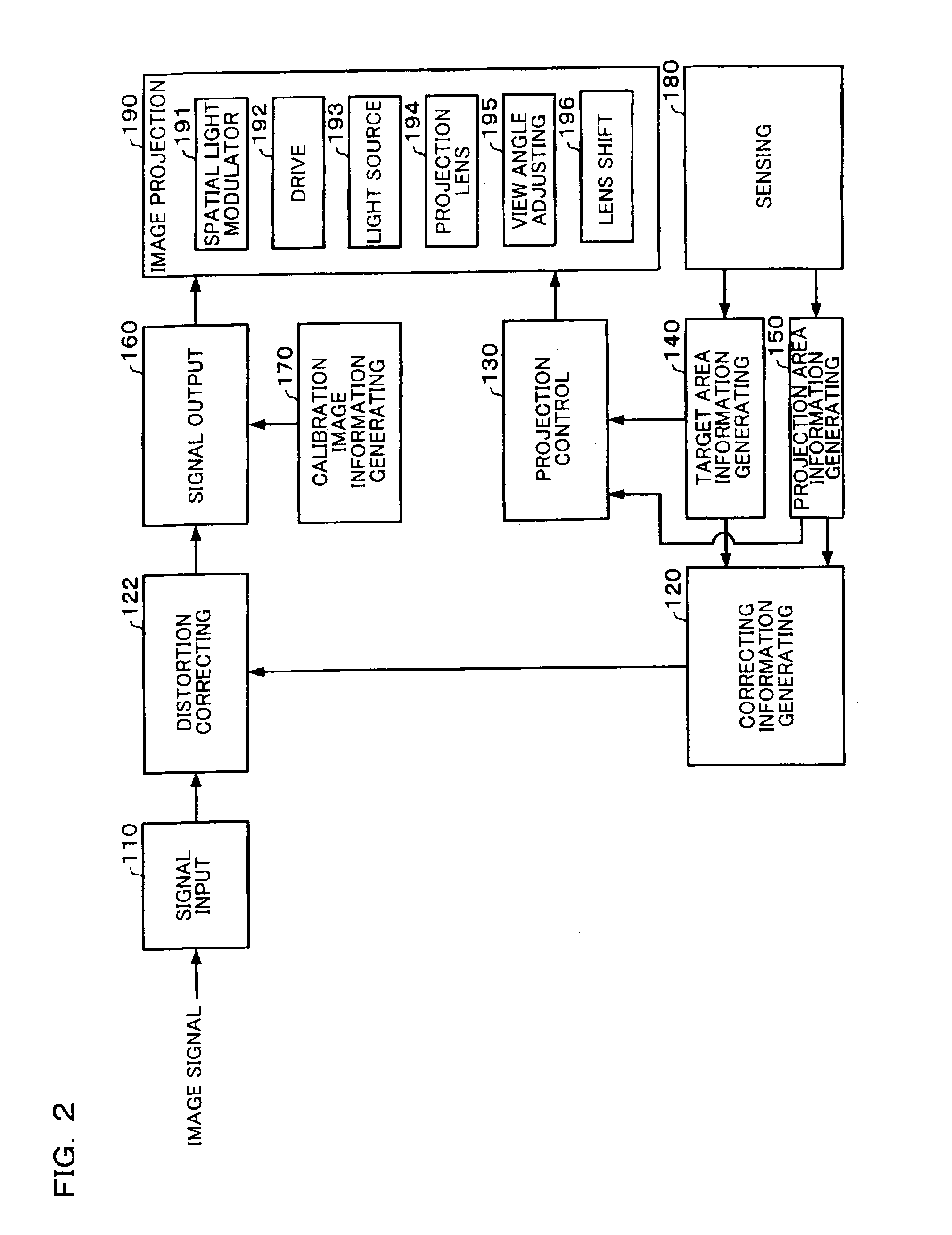
To provide an image processing system and others which can project an image more accurately and at higher speed while using a screen or the like as effectively as possible, there is provided a projector including a calibration image information generating section, an image projection section having a view angle adjusting section and a lens shift section for adjusting an optical axis of a projection lens to project the calibration image onto the screen or the like, a sensing section which senses a region including the projected calibration image and the screen or the like through a sensing surface to generate sensing information, a projection area information generating section which generates projection area information based on the sensing information, a target area information generating section which generates target area information based on the sensing information, and a projection control section which controls the view angle adjusting section and lens shift section based on the projection area information and the target area information.

Description

[0001]Japanese Patent Application No. 2003-182734, filed on Jun. 26, 2003, and Japanese Patent Application No. 2004-9026, filed on Jan. 16, 2004, are hereby incorporated by reference in their entirety.BACKGROUND OF THE INVENTION[0002]The present invention relates to an image processing system, projector, program, information storage medium and image processing method having a lens shift function and a zoom function.[0003]In order to display an appropriate image from an image projecting device such as a projector, it is necessary for the image projecting device to perform the adjustment of view angle (zoom adjustment), the adjustment of image display position and so on.[0004]In general, however, the adjustment of view angle and adjustment of image display position are performed by a user. This is very troublesome for the user.[0005]In addition, there is a case that an image is distorted to create a so-called keystone distortion in the vertical or horizontal direction depending on the...

Claims


Application Information

Patent Timeline
Patent Type & Authority Patents(United States)
IPC IPC(8): H04N5/74H04N17/00G02F1/13G03B21/00G06F3/033H04N9/31
CPCH04N5/74H04N9/3182H04N9/3185H04N9/3194H04N9/3197H04N9/31
Inventor WADA, OSAMUKOBAYASHI, MASANOBU
Owner SEIKO EPSON CORP
Learn More