Light conductive member, illuminating device having the same, and information processing apparatus having the illuminating device

a technology of light conductive parts and illuminating devices, which is applied in the direction of lighting and heating devices, instruments, machines/engines, etc., can solve the problems of not being able to achieve uniform illumination, not being able to accurately read the original text, and not being able to illuminate with sufficient light. , to achieve the effect of low cost, high illumination intensity and reduced power consumption

Inactive Publication Date: 2005-08-23
CANON KK
View PDF23 Cites 45 Cited by
  • Summary
  • Abstract
  • Description
  • Claims
  • Application Information

AI Technical Summary

Benefits of technology

[0024]An object of the present invention is to resolve drawbacks that the conventional illumination means employing a linear array of LED chips and the information processing apparatus utilizing such illumination means are unable to achieve a sufficiently low cost because of the large number of LED chips required and have a limit in the reduction of power consumption even with the use of LED's, and that an extremely uneven illumination state is obtained with a high illumination intensity on the original surface corresponding to the positions of the LED chips and a low intensity in the positions between the LED chips when the number of LED's is decreased in the LED array, or the illumination intensity on the original surface becomes uneven when the LED chips are positioned on the end faces of the translucent member, or an additional circuit is required for compensating the unevenness in the illumination intensity distribution, leading to a higher cost.
[0026]Still another object of the present invention is to provide an illuminating device of a high uniformity of the illumination intensity and a lower electric power consumption, allowing easy compactization, a light conductive member for use in such illuminating device and an information processing apparatus utilizing such illuminating device.
[0027]Still another object of the present invention is to provide an illuminating device of a high uniformity of the illumination intensity and a low electric power consumption, allowing easy compactization and cost reduction, adapted for use in the color image reading by switching the emission wavelength of the light source, a light conductive member for use in such illuminating device and an information processing apparatus utilizing such illuminating device.

Problems solved by technology

Consequently it becomes not only impossible to achieve uniform illumination but also there are generated portions which are not illuminated with the sufficient amount of light.
As the exact original reading becomes difficult under extremely uneven illumination, there has been a limit in the cost reduction by the decrease of the number of the LED chips.
However, such electric light bulb is associated with drawbacks that a high electric power consumption is required for obtaining a high illumination intensity, and that the device cannot be made compact because of the large amount of heat generation.
In addition, the service life of the electric bulb is considerably short, even in comparison with that of the fluorescent lamp, necessitating replacements as a result of decrease in the light intensity and filament breakage, so that a maintenance-free device as in the case of LED cannot be obtained.
(1) As the light sources are positioned longitudinally with the translucent member, the illuminating device becomes longer in comparison with the effective illuminating length of the translucent member;
(2) In case the amounts of light emission of the light sources on both ends are mutually different, the illumination intensity distribution becomes slanted, and the adjustment of the amounts of light emission of both light sources requires an additional cost;
(3) As the device is easily influenced by the longitudinal elongation or contraction of the translucent member, such influence has to be absorbed by the holding structure of the light sources, and, for this reason, it is difficult to achieve satisfactory heat dissipation;
(4) As the electric power supply has to be made to the light sources on both ends, an increased cost is required for the wirings; and
(5) In order to increase the illumination intensity for the entire device, it is necessary, for example, to increase the number of LED chips in the light sources. Such increase requires a corresponding increase of the light entrance face of the translucent member, thus resulting in a larger dimension of the illuminating device and the information processing apparatus.

Method used


Image

  • Light conductive member, illuminating device having the same, and information processing apparatus having the illuminating device
  • Light conductive member, illuminating device having the same, and information processing apparatus having the illuminating device
  • Light conductive member, illuminating device having the same, and information processing apparatus having the illuminating device

Examples


first embodiment

[0056][First Embodiment]

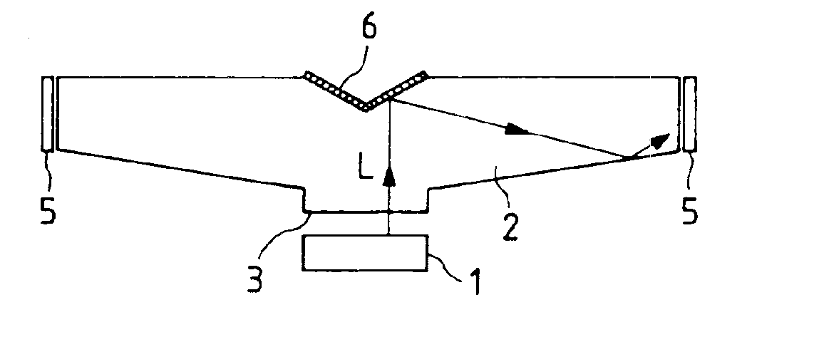
[0057]FIGS. 4A to 4C illustrate an illuminating device constituting a preferred embodiment of the present invention and are respectively a schematic plan view seen from an exit face side for the light beam, a schematic lateral view seen from the side of an end face in the longitudinal direction of a light conductive member and a schematic lateral view seen from the side of a light entrance face, and FIG. 4D is a chart showing an example of the illumination intensity distribution. Referring to FIGS. 4A to 4C, a translucent member 2 is provided with an entrance face 3 for introducing the light beam from a light source 1, on a part of a lateral face, and an area 6 provided in the opposite side, for reflecting and / or diffusing the light beam in the longitudinal direction of the translucent member 2. In FIG. 4A, it is illustrated in a recessed wedge shape, but it may have other shapes or may be replaced by a printed, coated or evaporated reflective film or by a co...

second embodiment

[0074][Second Embodiment]

[0075]FIGS. 5A to 5D show the illuminating device of another preferred embodiment of the present invention and are respectively a schematic plan view seen from the side of a light exit face, a schematic lateral view, a schematic plan view seen from the side of a light entrance face, and a chart showing an example of the illumination intensity distribution.

[0076]The basic configuration is same as that of the first embodiment shown in FIGS. 4A to 4C, and components equivalent to those in the first embodiment are represented by same numbers.

[0077]The present embodiment is featured by a fact, as shown in FIG. 5A, that the cross sectional area of the translucent member 2 decreases from the light entrance face 3 toward the end faces thereof.

[0078]This is because the proportion of the light beam, introduced from the entrance face 3 and propagating in the translucent member 2 by reflection or scattering in the area 6, entering the area 4 before reaching the ends of ...

third embodiment

[0084][Third Embodiment]

[0085]FIGS. 6A and 6B illustrate another embodiment of the translucent member of the illuminating device of the present invention, and are respectively a schematic cross-sectional view and a schematic perspective view. In the present embodiment, the translucent member is so formed that the cross sectional area decreases from the center toward both ends, and the exit face is formed as a convex lens 22 for condensing the light.

[0086]By forming the exit face as a convex lens form as light beam condensing means, the emitted illuminating light can be given directionality to increase the amount of the illuminating light.

[0087]The translucent member is shaped as a rectangular rod in the first embodiment, a rectangular rod with decreasing cross section toward the ends and a rod having a modified cross section including a convex lens in the third embodiment, but there may also be employed other shapes such as a cylindrical rod, a pentagonal or other polygonal rod, a c...


PUM


Abstract

For providing a compact illuminating device capable of uniform illumination with a high intensity, there is provided a light conductive member including a light entrance face provided in a part of a lateral face of a rod-shaped translucent member, an area provided on a side opposed to the light entrance face, for reflecting and / or diffusing the entered light in the longitudinal direction of the translucent member, and an exit face provided in at least a part of a lateral face other than those on which the area and the light entrance face are provided, for emitting at least a part of thus reflected and / or diffused light beam.

Description

CROSS-REFERENCE TO RELATED APPLICATION[0001]This application is a division of U.S. application Ser. No. 08 / 617,634, filed Mar. 19, 1996 now U.S. Pat. No. 6,015,200.BACKGROUND OF THE INVENTION[0002]1. Field of the Invention[0003]The present invention relates to a light conductive member, an illuminating device having the light conductive member, and an information processing apparatus having the illuminating device.[0004]2. Related Background Art[0005]For an illuminating device for the reading device of the information processing apparatus such as a facsimile apparatus, an electronic copying machine or the like, there has been employed a discharge tube such as a fluorescent tube or an LED array consisting of a linear array of a multitude of LED chips. Particularly in recent years, the use of the LED array has become popular as the demand for compacter and less expensive products is increasing with the increase of in-home use for example of the facsimile apparatus.[0006]An example of ...

Claims


Application Information

Patent Timeline
Patent Type & Authority Patents(United States)
IPC IPC(8): H04N1/03H04N1/031H04N1/04
CPCH04N1/031
Inventor OGURA, MAKOTO
Owner CANON KK
Why Eureka
Try Eureka