Turbine nozzle segment cantilevered mount

a technology for turbine nozzles and nozzle segments, which is applied in the direction of machines/engines, liquid fuel engines,foundry moulding apparatus, etc., can solve the problems of increasing chording stresses, reducing the durability of doublets, and increasing the non-uniformity of airfoil stresses

Active Publication Date: 2005-08-23
GENERAL ELECTRIC CO
View PDF19 Cites 39 Cited by
  • Summary
  • Abstract
  • Description
  • Claims
  • Application Information

AI Technical Summary

Benefits of technology

[0014]The above features of the nozzle segment allows it to be cantilever mounted and provide access for cooling air supply to the nozzle segment between first and second st...

Problems solved by technology

However, the longer chord length of the outer band and mounting structure compromises the durability of the doublet.
The longer chord length causes an increase of chording stresses due to the temperature gradient through the band and increased non-uniformity of airfoil stresses.
The trailing vane of a doublet typically sees significantly higher stresses which limits the life of the segment.
Due to the cantilevered design of the second stage nozzle, there ...

Method used


Image

  • Turbine nozzle segment cantilevered mount
  • Turbine nozzle segment cantilevered mount
  • Turbine nozzle segment cantilevered mount

Examples


Embodiment Construction

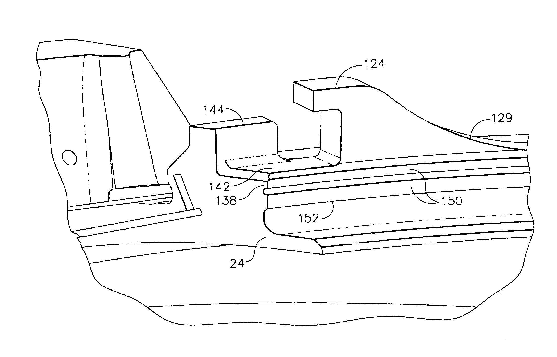
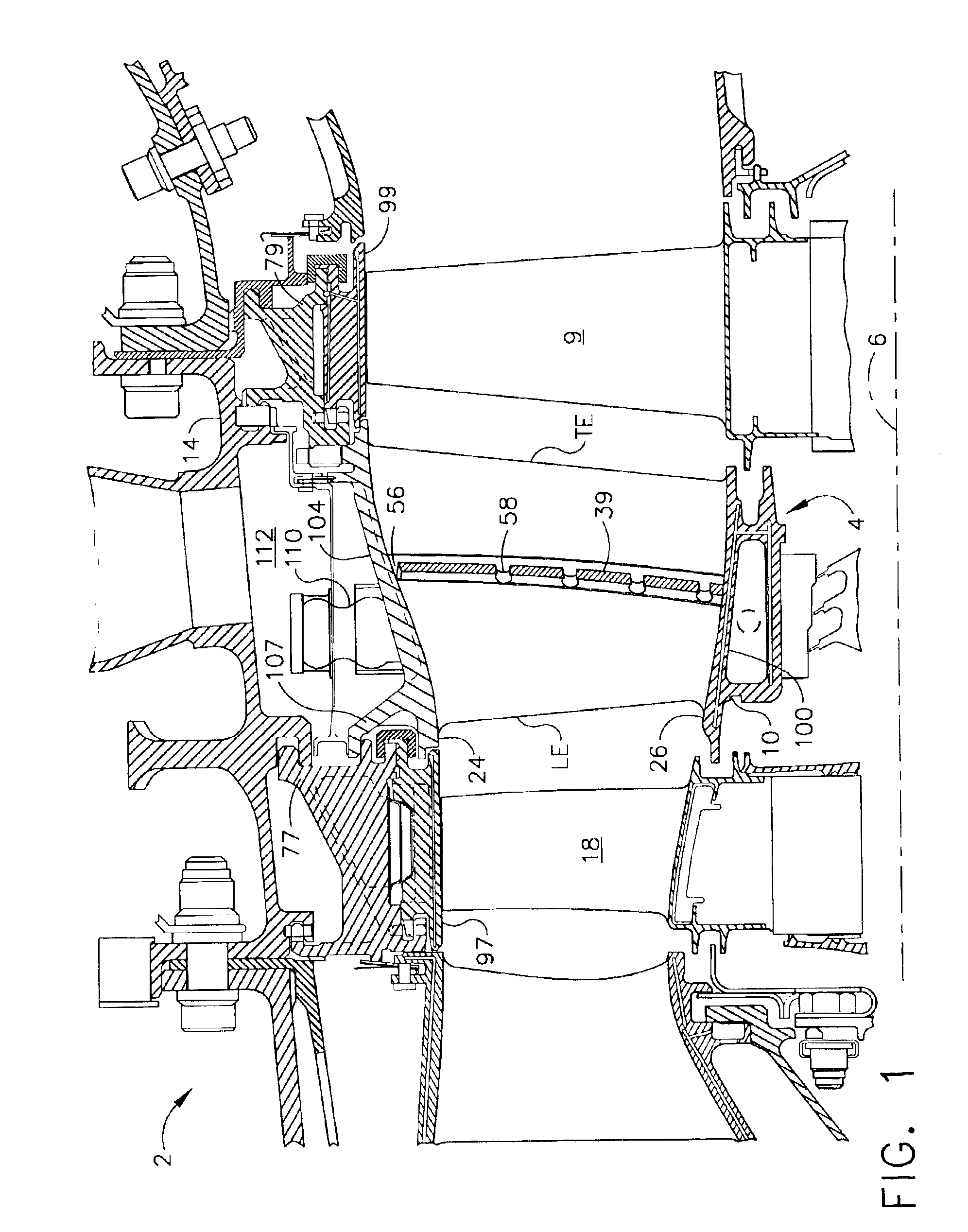
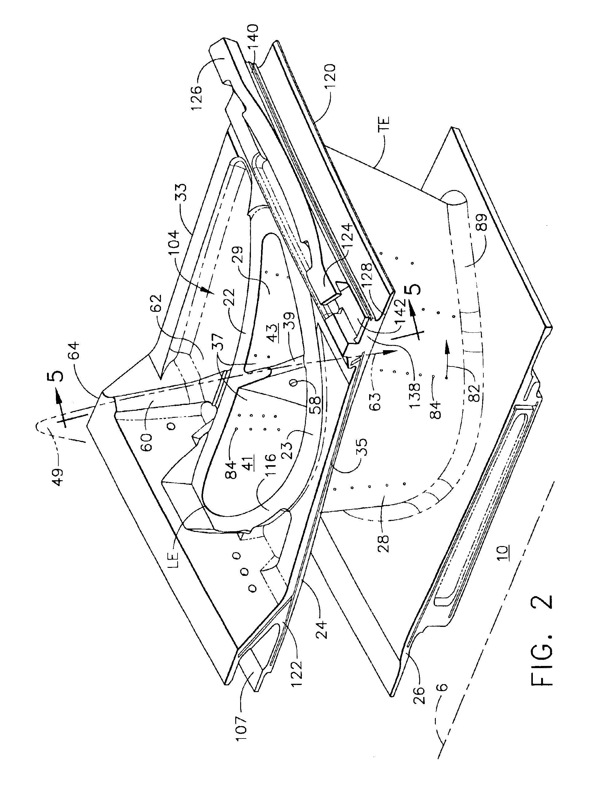
[0026]Illustrated in FIG. 1 is an exemplary second stage turbine nozzle 4 of an aircraft gas turbine engine high pressure turbine 2. The nozzle 4 is circumscribed about a longitudinal or axial centerline axis 6 and includes an annular casing 14 from which a plurality of nozzle segments 10 are cantilevered mounted. The nozzle segment 10 is disposed between an immediately upstream row of high pressure turbine first stage rotor blades 18 and an immediately downstream row of turbine second stage rotor blades 9. First and second shrouds 97 and 99 encircle the first and second stage turbine rotor blades 18 and 9 and are supported by first and second shroud supports 77 and 79, respectively, which depend radially inwardly from and are connected to the annular casing 14. The nozzle segments 10 are hooked by forward hooks 107 to the first shroud supports 77 and are cantilevered from the second shroud supports 79.

[0027]FIG. 2 illustrates one of the nozzle segments 10 including a single hollow ...


PUM


Abstract

A turbine nozzle segment includes at least one hollow airfoil extending radially between radially outer and inner band segments, a clockwise open hook on a clockwise end at an aft end of the outer band segment, and counter-clockwise open hook on a counter-clockwise end at the aft end of the outer band segments. An exemplary embodiment of the turbine nozzle segment includes a load stop extending radially outwardly from the outer band segment. At least one aftwardly facing load face is at the aft end of the nozzle segment at the outer band segment. The clockwise open hook is C-shaped and the counter-clockwise open hook is a shiplap hook. Another embodiment of the turbine nozzle segment has only one hollow airfoil with an airfoil wall surrounding a bifurcated cavity divided into forward and aft cavities by a bifurcating rib extending between pressure and suction sides of the airfoil wall.

Description

BACKGROUND OF THE INVENTION[0001]1. Field of the Invention[0002]The invention relates to mounting gas turbine engines turbine nozzle segments and, particularly, for cantilevered mounting of such segments.[0003]2. Description of Related Art[0004]In a typical gas turbine engine, air is compressed in a compressor and mixed with fuel and ignited in a combustor for generating hot combustion gases. The gases flow downstream through a high pressure turbine (HPT) having one or more stages including one or more HPT turbine nozzles and rows of HPT rotor blades. The gases then flow to a low pressure turbine (LPT) which typically includes multi-stages with respective LPT turbine nozzles and LPT rotor blades.[0005]The HPT turbine nozzle includes a plurality of circumferentially spaced apart stationary hollow nozzle vanes supported between radially outer and inner bands. Typically, a single chamber impingement baffle is inserted in each hollow airfoil to supply cooling air to the airfoil. Each ba...

Claims


Application Information

Patent Timeline
IPC IPC(8): F01D5/18F01D9/02F01D9/04F01D25/24F02C7/18
CPCF01D5/189F01D9/041F01D25/246B22C21/14E05Y2900/402Y02T50/67Y02T50/676F05D2240/12F05D2260/201F05D2260/22141F05D2260/30F05D2240/81Y02T50/60
Inventor POWIS, ANDREW CHARLESMCRAE, JR., RONALD EUGENECLARKE, JONATHAN PHILIPPETERMAN, JONATHAN JORDANFREDERICK, ROBERT ALANGIBLER, EDWARD EUGENEKEITH, BRIAN DAVID
Owner GENERAL ELECTRIC CO
Why Eureka
Try Eureka