Microcircuit cooling for a turbine blade tip

a technology of microcircuit cooling and turbine blades, which is applied in the direction of mechanical equipment, machines/engines, sustainable transportation, etc., can solve the problems of affecting the overall efficiency of the engine, and a large percentage of the work imparted to the airbled compressor, so as to improve the overall efficiency of the turbine and prolong the service li

Inactive Publication Date: 2005-08-23
RTX CORP
View PDF9 Cites 86 Cited by
  • Summary
  • Abstract
  • Description
  • Claims
  • Application Information

AI Technical Summary

Benefits of technology

[0011]The present invention provides a microcircuit cooling system that employs a new and effective approach to convectively cool a tip of an airfoil in combination with film cooling. In particular, this combination provides an advantage over the prior art tip cooling schemes in that, to achieve the same metal temperature at the tip, less cool compressor air is required to cool the tip. Less compressor bleed flow results in the additional advantage of providing an increase in turbine efficiency.
[0013]As described above, the present invention can be implemented and utilized in connection with many alternative airfoil (blade and vane) configurations. The combination of a) effective convective cooling provided by the micropassages and b) effective thermal insulation on the tip surface due to film cooling provides a cooler tip, as compared to conventional and current designs. Thus, an airfoil tip employing the beneficial cooling design of the present invention will not only have a longer service life but also improve overall turbine efficiency.

Problems solved by technology

A significant percentage of the work imparted to the air bled from the compressor, however, is lost during the cooling process.
The lost work does not add to the thrust of the engine and negatively effects the overall efficiency of the engine.
Further, film cooling is actively controlled in a complex and expensive manner.
Also, the fabrication and machining of an airfoil with film cooling holes adds a degree of complexity that is costly.
It will also be appreciated that once the cooling air exits the internal cavity of the airfoil and mixes with the hot gases, a severe performance penalty is incurred due to the mixing process and the different temperature levels of the mixing flows.
Thus, film cooling requires a greater amount of cooling air with the possibility of inadequate cooling of the outer surfaces of the airfoil.
In practice, it is still very difficult and very inconsistent to cool the blade tip in this manner due to the very complex nature of the cooling flow as it mixes with very dynamic hot gases of the mainstream flow.
This results in inadequate cooling of tip cap and eventual temperature inflicted degradation of tip cap.
Cooling air used to accomplish this is expensive in terms of overall fuel consumption.

Method used


Image

  • Microcircuit cooling for a turbine blade tip
  • Microcircuit cooling for a turbine blade tip
  • Microcircuit cooling for a turbine blade tip

Examples


Embodiment Construction

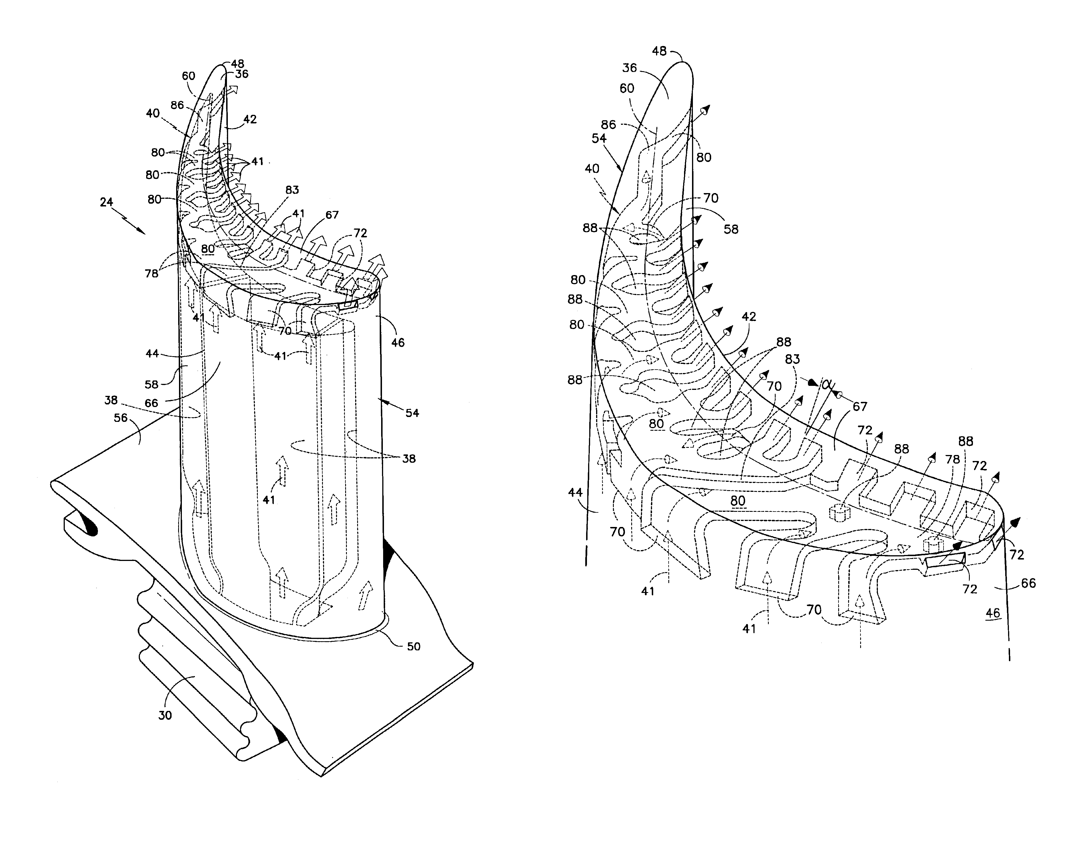
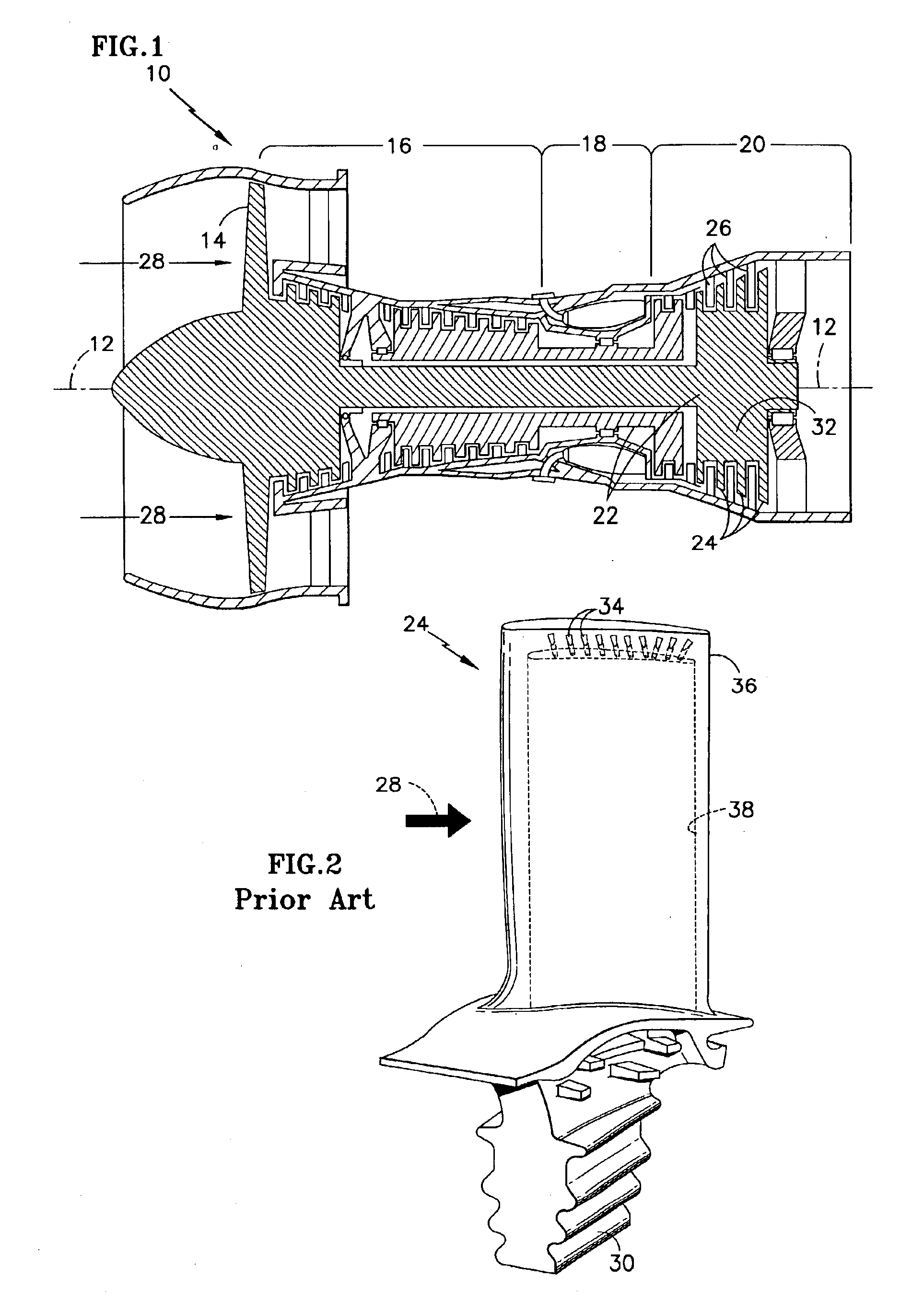
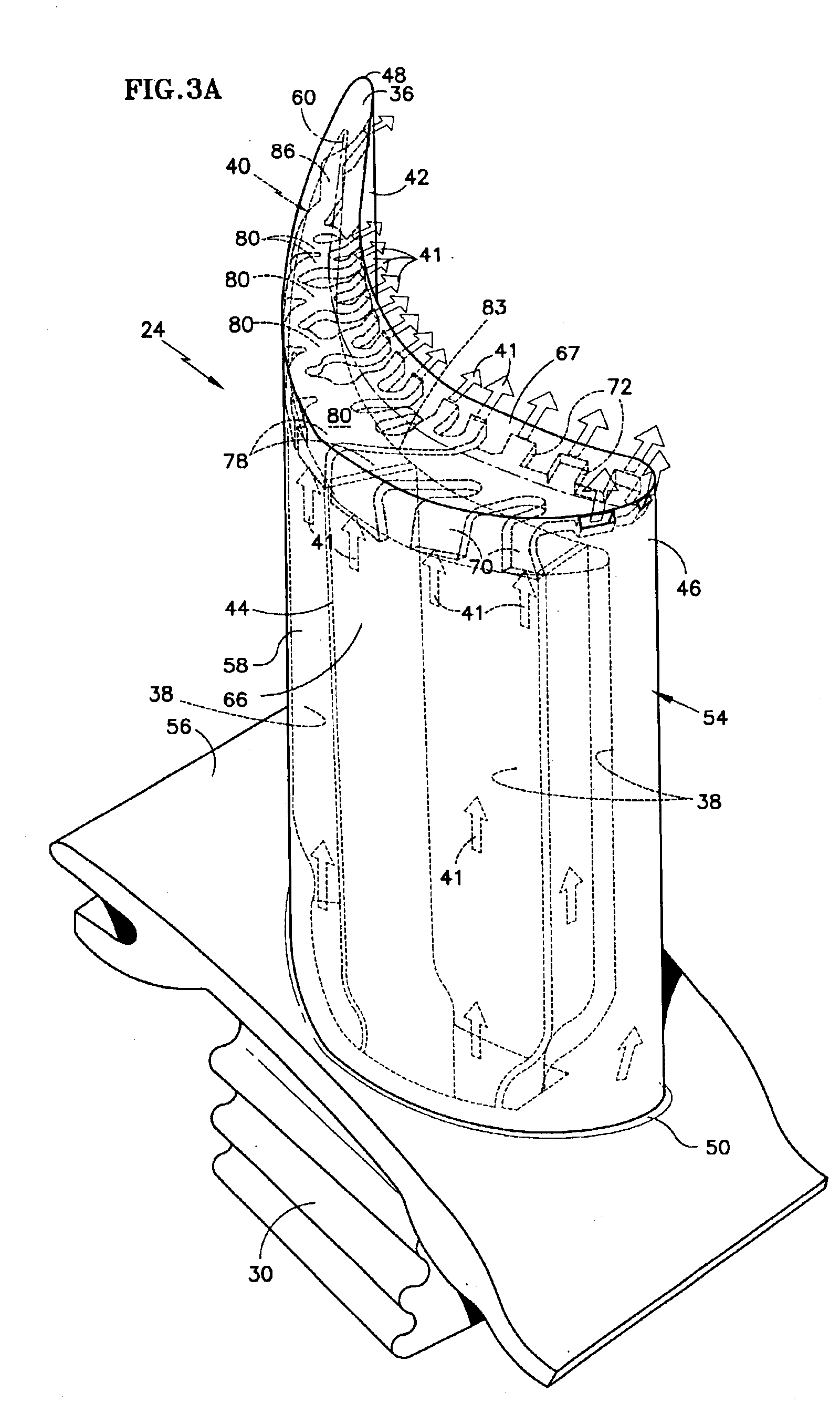
[0022]A gas turbine engine 10, such as a gas turbine used for power generation or propulsion, circumferentially disposed about an engine centerline, or axial centerline axis 12 is shown. The engine 10 includes a fan 14, a compressor 16 (FIG. 1), a combustion section 18 and a turbine 20. As is well known in the art, air compressed in the compressor 16 (FIG. 1) is mixed with fuel which is burned in the combustion section 18 and expanded in turbine 20. The air compressed in the compressor 16 (FIG. 1) and the fuel mixture expanded in the turbine 20 can both be referred to as a hot gas stream flow (hot combustion gases, gas flow) 28. The turbine 20 includes rotors 22 which, in response to the expansion, rotate driving the compressor 16 (FIG. 1) and fan 14. The turbine 20 comprises alternating rows of rotary airfoils or blades 24 and static airfoils or vanes 26. The use of the system of FIG. 1 is for illustrative purposes only and is not a limitation of the instant invention which may be ...


PUM


Abstract

An improved cooling design and method for cooling airfoils within a gas turbine engine is provided which includes an embedded microcircuit that traverses a tip between a suction sidewall and a pressure sidewall of the airfoil. The microcircuit includes at least on inlet disposed proximate to the tip and one of the sidewalls for receiving cooling air from an internal cooling cavity of the airfoil and at least outlet disposed proximate to the tip through which the cooling air ejects into a region outside the airfoil.

Description

[0001]The government may have rights in this invention, pursuant to Contract Number F33615-02-C-2202, awarded by the United States Air Force, Wright Patterson Air Force Base.TECHNICAL FIELD[0002]This invention relates to coolable airfoils of the type used in high temperature rotary machines such as gas turbines and, more particularly, to an improved tip cooling scheme for airfoils.BACKGROUND OF THE INVENTION[0003]Efficiency is a primary concern in the design of any gas turbine engine. Historically, one of the principle techniques for increasing efficiency has been to increase the gas path temperatures within the engine. Using internally cooled components made from high temperature capacity alloys has accommodated the increased temperatures. Turbine stator vanes and blades, for example, are typically cooled using compressor air worked to a higher pressure, but still at a lower temperature than that of the core gas flow passing by the blade or the vane. It will be understood that comp...

Claims


Application Information

Patent Timeline
Patent Type & Authority Patents(United States)
IPC IPC(8): F01D5/18F01D5/08F01D5/30F02C7/18
CPCF01D5/18F01D5/187F01D5/20Y02T50/676F05D2260/2212Y02T50/60F01D5/08
Inventor CUNHA, FRANKDUBE, BRYAN
Owner RTX CORP
Why Eureka
Try Eureka