Blade damper

a damper and blade technology, applied in the field of turbines, can solve problems such as the relative motion of adjacent blades

Inactive Publication Date: 2005-08-23
RTX CORP
View PDF11 Cites 42 Cited by
  • Summary
  • Abstract
  • Description
  • Claims
  • Application Information

AI Technical Summary

Benefits of technology

[0008]Another aspect of the invention involves a turbomachine blade combination. First and second blades each have a root, an airfoil outboard of the root, and a platform and neck between the root. The combined platform and neck has first and second sides, the first side of one of the blades facing the second side of the other. Means are mounted in at least one pocket of at least one of the facing first and second sides for damping relative motion of the first and second blades and sealing against combustion gas upstream infiltration.

Problems solved by technology

Thermal and mechanical stresses and wear can produce relative motion of adjacent blades.

Method used


Image

  • Blade damper
  • Blade damper
  • Blade damper

Examples


Embodiment Construction

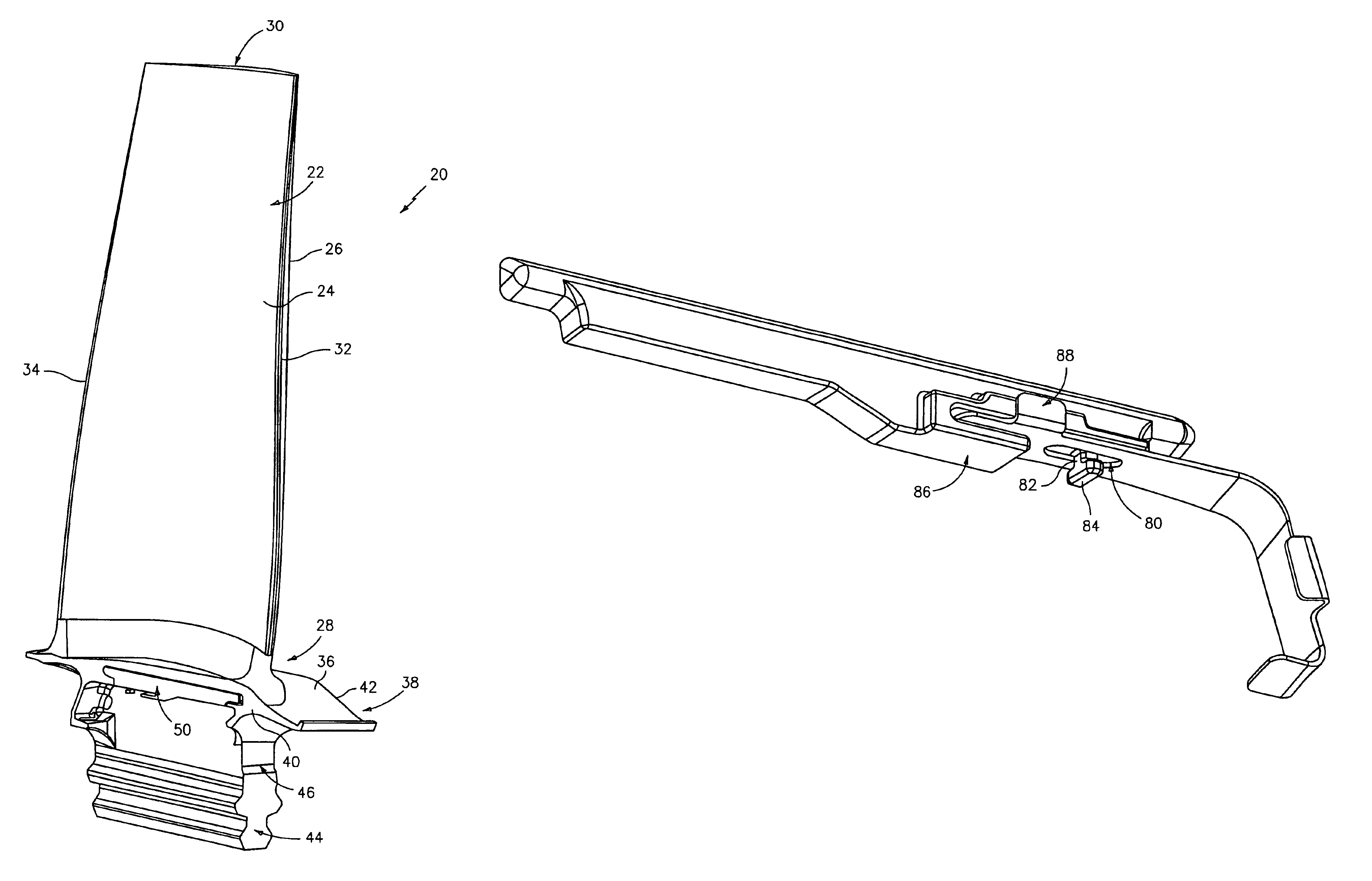
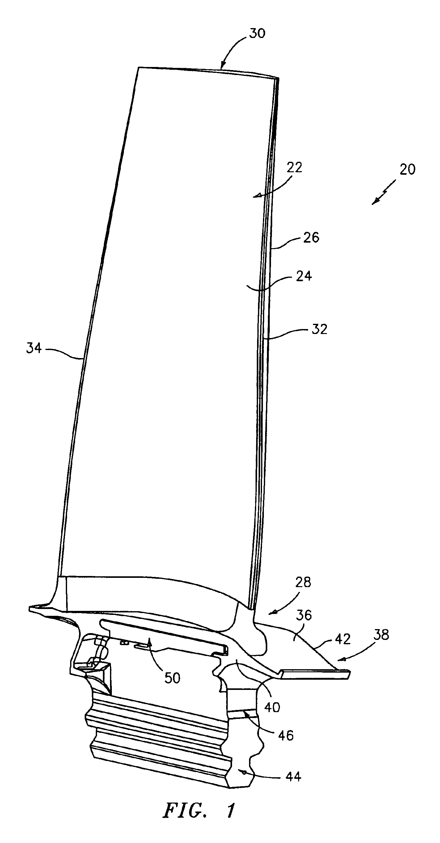
[0024]FIG. 1 shows a blade 20 having an airfoil 22 with concave pressure and convex suction side surfaces 24 and 26 extending from an airfoil root 28 to an airfoil tip 30 and between leading and trailing edges 32 and 34. The airfoil root is formed at an outboard surface 36 of a platform 38 having first and second sides 40 and 42. The platform is outboard of a convoluted root 44 and separated therefrom by a neck 46. A wedge damper / seal assembly 50 is partially accommodated within a compartment in the platform and neck combination.

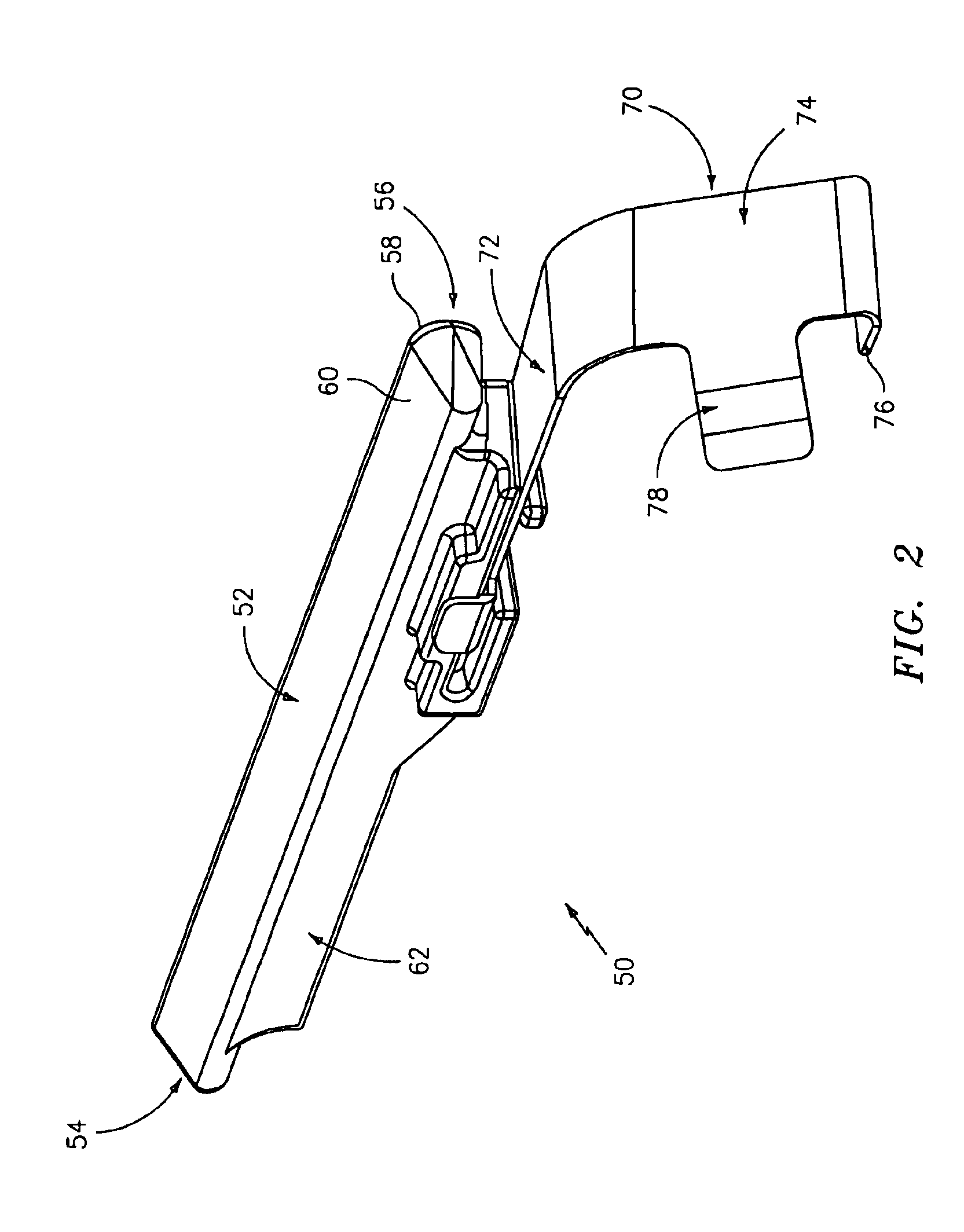
[0025]FIG. 2 shows further features of the exemplary damper / seal assembly 50. A main body portion of a damper member 52 extends from an upstream end 54 to a downstream end 56 and has first and second damping surfaces 58 and 60. An underhung mass 62 depends inboard from the main portion of the damper member. A seal member 70 has an outboard shelf portion 72 for engaging the damper member. A depending portion 74 depends generally inboard from the shelf 72 and ...


PUM


Abstract

A turbomachine blade damper has a damper member with first and second damping surfaces for respectively engaging first and second surfaces of adjacent first and second blades. The damper has a seal having a first portion engaged in the damper member to resist relative movement of the seal in at least one direction and a second portion engaging at least one of the blades and advantageously forming a seal to resist upstream gas infiltration.

Description

U.S. GOVERNMENT RIGHTS[0001]The invention was made with U.S. Government support under contract N00019-02-C-3003 awarded by the U.S. Navy. The U.S. Government has certain rights in the invention.BACKGROUND OF THE INVENTION[0002](1) Field of the Invention[0003]The invention relates to turbomachinery. More particularly, the invention relates to dampers for damping relative motion of adjacent blades in a turbomachine rotor.[0004](2) Description of the Related Art[0005]A typical gas turbine engine has, in its compressor and turbine sections a number of blade-carrying disks that rotate about the engine axis and are interspersed with arrays of vanes that do not. The periphery of each disk may have a circumferential array of convoluted blade retention slots which receive complementary root portions of associated blades. Neck portions of the blades extend outward to platform sections which have outboard surfaces that help to locally define an inboard surface of the core flowpath through the ...

Claims


Application Information

Patent Timeline
Patent Type & Authority Patents(United States)
IPC IPC(8): F01D11/00F01D5/12F01D5/22F01D5/26F04D29/08F04D29/38
CPCF01D5/22F01D11/008F05D2230/60Y10S416/50F05D2260/30
Inventor SURACE, RAYMONDCOLON, DENNIS I.
Owner RTX CORP
Why Eureka
Try Eureka