Two-piece model and die system

a model and die technology, applied in the field of dental care, can solve the problems of reducing the skill level of dentists, affecting the patient's comfort, and the patient's inability to wear crown or dentures, so as to reduce the time required and lower the skill level

Inactive Publication Date: 2005-08-23
GBASE INC
View PDF16 Cites 21 Cited by
  • Summary
  • Abstract
  • Description
  • Claims
  • Application Information

AI Technical Summary

Benefits of technology

[0027]At least one cast tooth having a pair of pins depending therefrom and snugly received within associated bores of said first and second rows of bores formed in the working quadrant is positioned so that a leading surface of the at least one cast tooth is substantially flush with the preselected leading edge of the working quadrant. This minimizes trimming of excess materials.
[0038]An important object of this invention is to provide an improved model and die system that lowers the level of skill required to produce a good set of model teeth.
[0039]A closely related object is to provide an improved system that substantially reduces the time required to produce a good set of model teeth.

Problems solved by technology

Errors can arise, however, when a bite registration is transferred from a triple tray impression to an articulation hinge such as a Vertex®, Orbiz®, Quickulator®), or to a generic metal articulation hinge.
The crown or denture being prepared will not fit the patient if the sections and dies do not seat all the way flat into the working quadrant stone.
This method is very labor-intensive and mistakes at any step can result in a substandard working model.
For example, it is difficult to always achieve the optimal water and powder ratio to produce the working quadrant stone.
Further steps that are difficult to optimize include the grinding of the model, the placement and gluing of the dowel pins, and the articulation of the models to produce proper occlusion in the mouth.
Further difficulties include breaking the model during drilling or trimming of holes which necessitates re-starting the process from the beginning, and the optimization of many other variables not expressly mentioned herein but well-known to those who work in this field.
Moreover, the model has been placed in the center of the tray but this technique has the disadvantage of making the prep hard to reach and hard to see.
Most of the known systems prevent the technician from determining whether or not the dies are completely seated.
Moreover, in all of the known systems it is difficult to put in and take out the dies from the working quadrant.
Most known systems do not provide good centric opposing quadrants for occlusion nor do they provide a free and centric opposing quadrant.
Nor does any known system employ double dowel pins to stabilize dies.
There are no offset, preformed bores that enables the efficient trimming of excess casting material.

Method used


Image

  • Two-piece model and die system
  • Two-piece model and die system
  • Two-piece model and die system

Examples


first embodiment

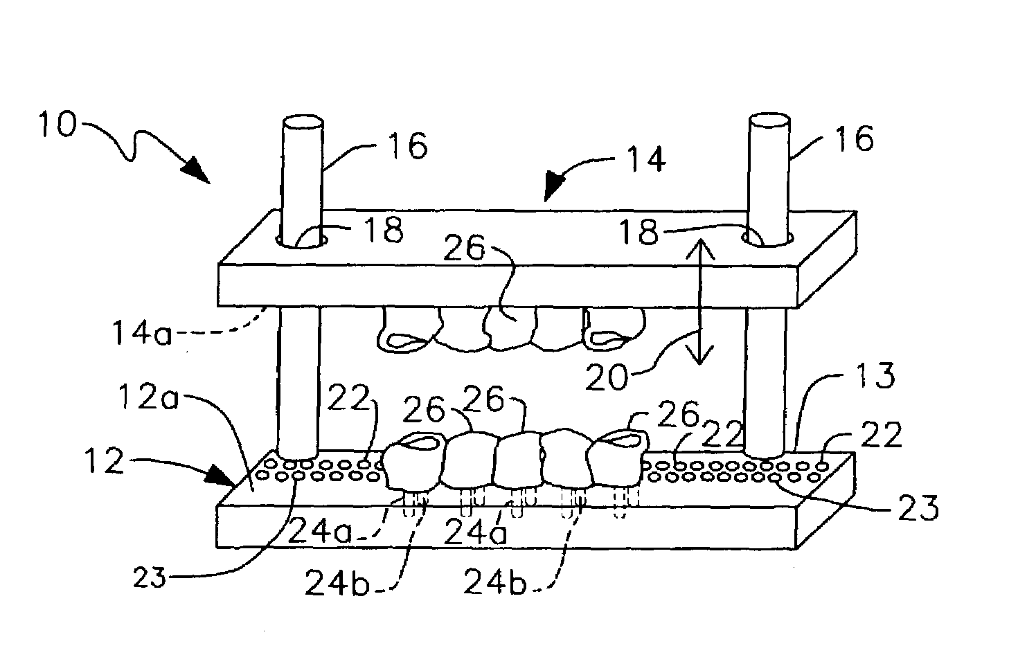
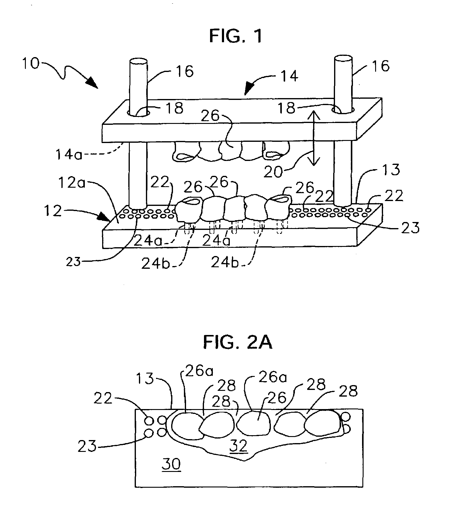
[0057]novel system 10 includes a working base or quadrant 12 and an opposing top member or opposing quadrant 14 having essentially the same structure as working quadrant 12. More particularly, working quadrant 12 and opposing quadrant 14 share a generally straight, parallelepiped configuration having a predetermined length, width, and height.

[0058]Working quadrant 12 has a flat upper surface 12a and opposing quadrant 14 has a flat lower surface 14a. Flat upper surface 12a is disposed in confronting relation to lower flat surface 14a.

[0059]In a first embodiment, a pair of upstanding guideposts, collectively denoted 16, interconnects working quadrant 12 and opposing quadrant 14. The respective lowermost ends of guideposts 16 are secured to working quadrant 12 by any suitable means, near opposite ends thereof. Two longitudinally spaced apart throughbores 18 are formed in opposing quadrant 14 to slidingly receive said posts so that opposing quadrant 14 may be easily moved toward or awa...

third embodiment

[0079]FIGS. 8A, 8B, and 8C depict a third embodiment where a working base 50 has the same structure as working quadrant 12 but is semicircular in configuration. As such, it represents a full lower set of teeth and not just a quadrant as in the first two embodiments. Opposing top member 52 also has the same structure as opposing quadrant 14 in all respects except that said opposing top member is semicircular and represents a full set of upper teeth and not just a quadrant as in the first two embodiments. The same reference numerals are used in view of the common structure of the three embodiments.

[0080]The novel structure thus removes much of the guesswork associated with prior art techniques. Thus, the level of skill required to make a good set of model teeth is substantially reduced. Much less time is required as well. A lab equipped with the novel system will also become known for its consistency and reliability. Moreover, patient complaints about ill-fitting crowns and dentures w...


PUM


Abstract

A model and die system has a working quadrant of parallelepiped construction and a opposing quadrant of the same construction. The working quadrant has an upper flat surface disposed in confronting relation to a lower flat surface of the opposing quadrant. Pin-receiving bores are formed in the working quadrant and mounting members depend from the opposing quadrant. Each cast tooth supported by the working quadrant has a pin depending from it and is fully seatable against the upper flat surface. Each cast tooth mounted on the upper flat surface is secured to a mounting post that depends from the upper flat surface. In a first embodiment, the quadrants are held in spaced apart, adjustable vertical relation to one another by a pair of parallel guideposts. In a second embodiment, an articulated hinge performs that function. In a third embodiment, a semicircular base opposes a semicircular top member.

Description

BACKGROUND OF INVENTION[0001]1. Field of the Invention[0002]This invention relates, generally, to dentistry. More particularly, it relates to a model and die system for making casts of dental impressions for the shaping of crowns and dentures.[0003]2. Description of the Prior Art[0004]The use of triple trays is now the most common technique for taking impressions. Also known as dual-arch trays, they capture the area to be restored, the opposing area, and the bite relationship. Errors can arise, however, when a bite registration is transferred from a triple tray impression to an articulation hinge such as a Vertex®, Orbiz®, Quickulator®), or to a generic metal articulation hinge.[0005]The current method for transferring a bite registration from a triple tray to an articulation hinge includes the initial step of mixing dental stone powder to make a batch of liquid dental stone and pouring the liquid dental stone into the impression on the prep side first. The stone is allowed to cu...

Claims


Application Information

Patent Timeline
Patent Type & Authority Patents(United States)
IPC IPC(8): A61C11/00A61C9/00A61C11/02
CPCA61C9/002A61C11/001A61C11/02
Inventor GAGLIANO, JAMES SALVATORESTEELE, IV, GAVIN ATLAS
Owner GBASE INC
Why Eureka
Try Eureka