Variable-mold-clamping-force pipe internal high-pressure forming device and method

A technology of internal high pressure forming and clamping force, which is applied in the field of internal high pressure forming of pipes, to achieve the effect of reducing machine tonnage, reducing manufacturing costs and reducing performance requirements

Active Publication Date: 2013-07-24
NINGBO POWER PRECISION HYDRAULIC MACHINERY
View PDF7 Cites 11 Cited by
  • Summary
  • Abstract
  • Description
  • Claims
  • Application Information

AI Technical Summary

Problems solved by technology

[0004]The purpose of this invention is to overcome the high pressure required for high pressure forming in the traditional constant clamping force pipe, the requirements for machine performance, mold performance, sealing performance, and mold lubrication performance High machine cost, easy mold lifting, high pressure of forming parts, inability to form complex parts with large deformation, low work efficiency, etc., to provide a mold with small clamping force, low pressure requirements for forming medium, and high performance requirements for machines and molds High-efficiency and high-production-efficiency new tube high-pressure forming method with variable clamping force

Method used


Image

  • Variable-mold-clamping-force pipe internal high-pressure forming device and method
  • Variable-mold-clamping-force pipe internal high-pressure forming device and method

Examples


Embodiment Construction

[0023] Now in conjunction with accompanying drawing and embodiment the present invention is described in further detail:

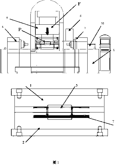
[0024] Such as figure 1 The structure shown: 1 is the upper mold, 2 is the lower mold, 3 is the mold cavity, 4 is the left push head, 5 is the right push head, 6 is the supercharger, 7 is the tube blank, 8 is the liquid filling device, 9 Be movable beam, 10 is water injection channel. F is the clamping force, and P is the working pressure of the mold cavity.

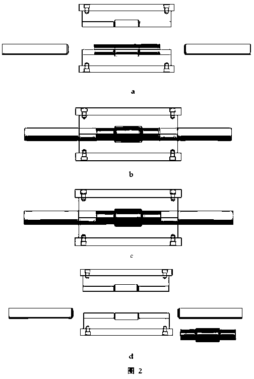
[0025] First, the original position, the upper mold is in the upper position, the lower mold is in the lower original position, the left and right push heads are in the left and right original positions, and the tube blank is in the lower mold cavity (such as figure 2 shown in a). When working, the movable crossbeam of the hydraulic press is molded and pressurized. When the set initial signaling pressure is reached, the side push cylinder drives the left and right push heads forward. When the no...


PUM


Abstract

The invention relates to a variable-mold-clamping-force pipe internal high-pressure forming method, which comprises the steps that after an upper mold and a lower mold are clamped, forming media with certain pressure is filled into a mold cavity, pushing heads on a left side and a right side simultaneously push pipe blanks into the mold cavity from the left side and the right side, the pipe blanks are pressed into the mold cavity to be formed through internal pressurization and axial force application and material compensation under the joint effect of the pressure of the forming media and the material compensation of the pushing heads, and finally the pipe blanks are in fit with the mold cavity to realize part formation. Since different mold clamping forces are adopted at different stages, the defects that the pressure required by the traditional constant-mold-clamping-force tube internal high-pressure forming method is high, the requirements on machine performance, mold performance, sealing performance and mold lubricating performance are high, the machine cost is high, the situation of mold lifting is apt to occur, the part forming pressure is high, large-deformation complex parts cannot be formed, the working efficiency is low and the like are overcome.

Description

technical field [0001] The invention belongs to the technical field of internal high-pressure forming of pipes, in particular to a forming method for internal high-pressure forming of pipes. Background technique [0002] The internal high pressure forming of the pipe is to fill the mold cavity with a certain pressure of forming medium after the upper and lower molds are closed. Cavity, under the joint action of the pressure of the forming medium and the feeding of the push head, the tube blank is pressed into the cavity of the mold through internal pressure and axial force feeding, so as to realize an advanced forming method for part forming. Compared with the traditional forming method, this forming method has the advantages of light weight, saving materials, reducing the amount of subsequent machining and assembly welding, reducing the number of parts and molds, reducing mold costs, high surface quality and mechanical properties of parts, high fatigue strength, and good ...

Claims


Application Information

Patent Timeline
Patent Type & Authority Applications(China)
IPC IPC(8): B21D26/033B21D26/039
Inventor 李百炼刘文蒋广军尹修修张林优
Owner NINGBO POWER PRECISION HYDRAULIC MACHINERY
Why Eureka
Try Eureka