Dielectric phase shifter with novel conducting cavities

A phase shifter and dielectric technology, which is applied to waveguide-type devices, electrical components, circuits, etc., can solve the problems of large solder joint stress on inner conductors and corresponding pads, deterioration of electrical indicators and intermodulation, and inability to take mechanized methods. Achieve the effect of improving welding economy, reducing the risk of deformation by external force, and reducing potential intermodulation points

Active Publication Date: 2016-11-02
WUHAN HONGXIN TELECOMM TECH CO LTD
View PDF5 Cites 10 Cited by
  • Summary
  • Abstract
  • Description
  • Claims
  • Application Information

AI Technical Summary

Problems solved by technology

However, in the actual welding operation, due to the existence of the insulator and inner conductor bent at 90°, and the limitation of the circuit board in the length direction through the solder joints of the PCB pad, the slight swing of the coaxial cable and the slight displacement of the circuit board, It is easy to cause excessive stress on the inner conductor and the corresponding pad solder joint, resulting in deterioration of electrical indicators and intermodulation
In order to avoid excessive stress on the inner conductor and the solder joint of the corresponding PCB pad, the method of cutting and b

Method used


Image

  • Dielectric phase shifter with novel conducting cavities
  • Dielectric phase shifter with novel conducting cavities
  • Dielectric phase shifter with novel conducting cavities

Examples


Embodiment Construction

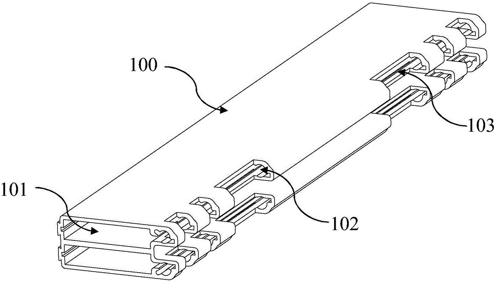
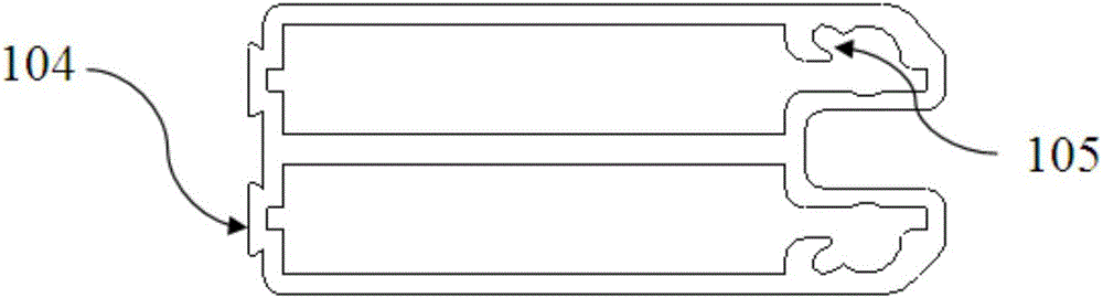
[0051] The present invention mainly adopts following technical scheme:

[0052] The cavity of the phase shifter is made of aluminum alloy extruded profile structure. The profile is divided into two rectangular cavities. There is a conduction cavity on one side of each single cavity, which is connected with the single cavity. There are two vertical cavity on the other side of the profile. Ribs for structural fixation. The conduction cavity is hollow with a circular hole with a diameter of 3.6mm, which can be matched with the outer conductor of the coaxial cable for welding. One side of the hole is a small groove with a width of 1.2mm, which can be used for tin entry and tinning, and passes through during welding. Reduce the conduction area to slow down the welding heat transfer. The 4 joints of the outer conductor of the coaxial cable in the external conduction chamber of the profile, the reserved width remains the same, and the other width 15mm is machined down to remove it, ...


PUM


Abstract

The invention discloses a dielectric phase shifter with novel conducting cavities. The dielectric phase shifter includes an outer shell, dielectric sheets, a circuit board and coaxial cables; two rectangular cavities are formed in the outer shell; one conducting cavity is formed at one side of each cavity, wherein the conducting cavity is connected with the cavity; each conducting cavity is hollow and is a circular hole of which the diameter is 3.6 mm, and a small groove of which the width is 1.2 mm formed at one side of the hole; in each conducting cavity 4, a portion with a reserved width is maintained to be original at a position where the outer conductor of a corresponding coaxial cable is welded to the conducting cavity 4, and a portion of which the width is 15mm is machined downwards so as to be removed, and therefore, the coaxial cable can extend into the conducting cavity so as to be welded to the conducting cavity; the circuit board is designed into a rectangle with four grooves formed at one side; and the four grooves are corresponding to the edges of circuit board pads for welding the inner conductors of the coaxial cables. When welding is carried out, only one-time clamping is required, and therefore, a welding technique is better, and the economical efficiency of welding is improved; and the conducting cavities are utilized to excellently wrap the outer conductors of the coaxial cables, distortion can be avoided, bending stress of the coaxial cables can be avoided, the risk that welding spots and the circuit board are damaged can be lowered, and hidden hazard points in intermodulation can be decreased.

Description

technical field [0001] The invention relates to the field of base station antennas for mobile communications, in particular to the field of phase shifters for base station antennas, in particular to a novel dielectric phase shifter for conductive cavities. Background technique [0002] In a wireless communication system, the base station antenna is the interface between the transceiver and the external propagation medium. With the development of wireless communication, the complex and changeable network environment and the shortage of site and steel structure communication tower platform resources, the requirements for base station antennas are usually higher. The electronically adjustable antenna can realize the continuous adjustment of the downtilt angle of the vertical beam, and the network coverage is more flexible. The beam inclination angle of the electronically adjustable antenna can be changed through remote control as needed, and the coverage effect is better than ...

Claims


Application Information

Patent Timeline
IPC IPC(8): H01P1/18H01Q3/32
CPCH01P1/18H01Q3/32
Inventor 程季张申科吴卫华赖青松汪振宇
Owner WUHAN HONGXIN TELECOMM TECH CO LTD
Why Eureka
Try Eureka