
Coaxial connector with RF switch

a technology of coaxial connector and switch, which is applied in the direction of coupling device connection, coupling device details, two-pole connection, etc., can solve the problems of increased failure rate, poor contact between the terminals, and reduced assembly productivity, so as to prevent poor contact with the fixed terminal

Inactive Publication Date: 2005-08-23
HECTO
View PDF6 Cites 30 Cited by
  • Summary
  • Abstract
  • Description
  • Claims
  • Application Information

AI Technical Summary

Benefits of technology

[0009]Accordingly, the present invention is conceived to solve the aforementioned problems of the conventional coaxial connector. It is an object of the present invention to provide a coaxial connector wherein the productivity of assembly is enhanced by allowing assembly work to be simplified and the durability of products is improved by reducing the stress exerted on terminals.
[0011]According to the coaxial connector of the present invention configured as above, since the movable and fixed terminals are insert molded in the insulated housing when the insulated housing is injection molded, additional assembly processes are not required. Therefore, the productivity of assembly can be enhanced, the occurrence of failure due to assembly work made by unskilled workers can be prevented, and the quality of products can also be uniformly maintained.

Problems solved by technology

However, as mobile phones have become miniaturized, the conventional coaxial connectors have further microminiaturized.
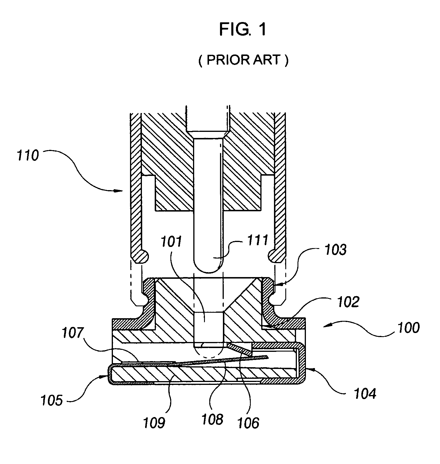
Accordingly, there is a problem in that when the assembled coaxial connector is mounted on the surface of a circuit board, flux flows into the terminal through the gap between the terminal and the groove of the insulated housing and thus poor contact is produced between the terminals.
Further, there are other problems in that the failure rate is increased due to difficulty in assembling the microminiaturized parts with one another and the productivity of assembly is also reduced due to the increased number and complexity of the assembling processes.
Therefore, when the coaxial connector performs a switching operation by means of a force produced by the central conductor 111 of the coaxial plug 110, a great amount of stress is repeatedly exerted on the bent portion of the movable terminal and elastic characteristics are easily lost.
Accordingly, there is another problem in that service life of the coaxial connector is short.

Method used


Image

  • Coaxial connector with RF switch
  • Coaxial connector with RF switch
  • Coaxial connector with RF switch

Examples


Embodiment Construction

[0021]Hereinafter, a preferred embodiment of a coaxial connector according to the present invention will be described in detail with reference to the accompanying drawings.

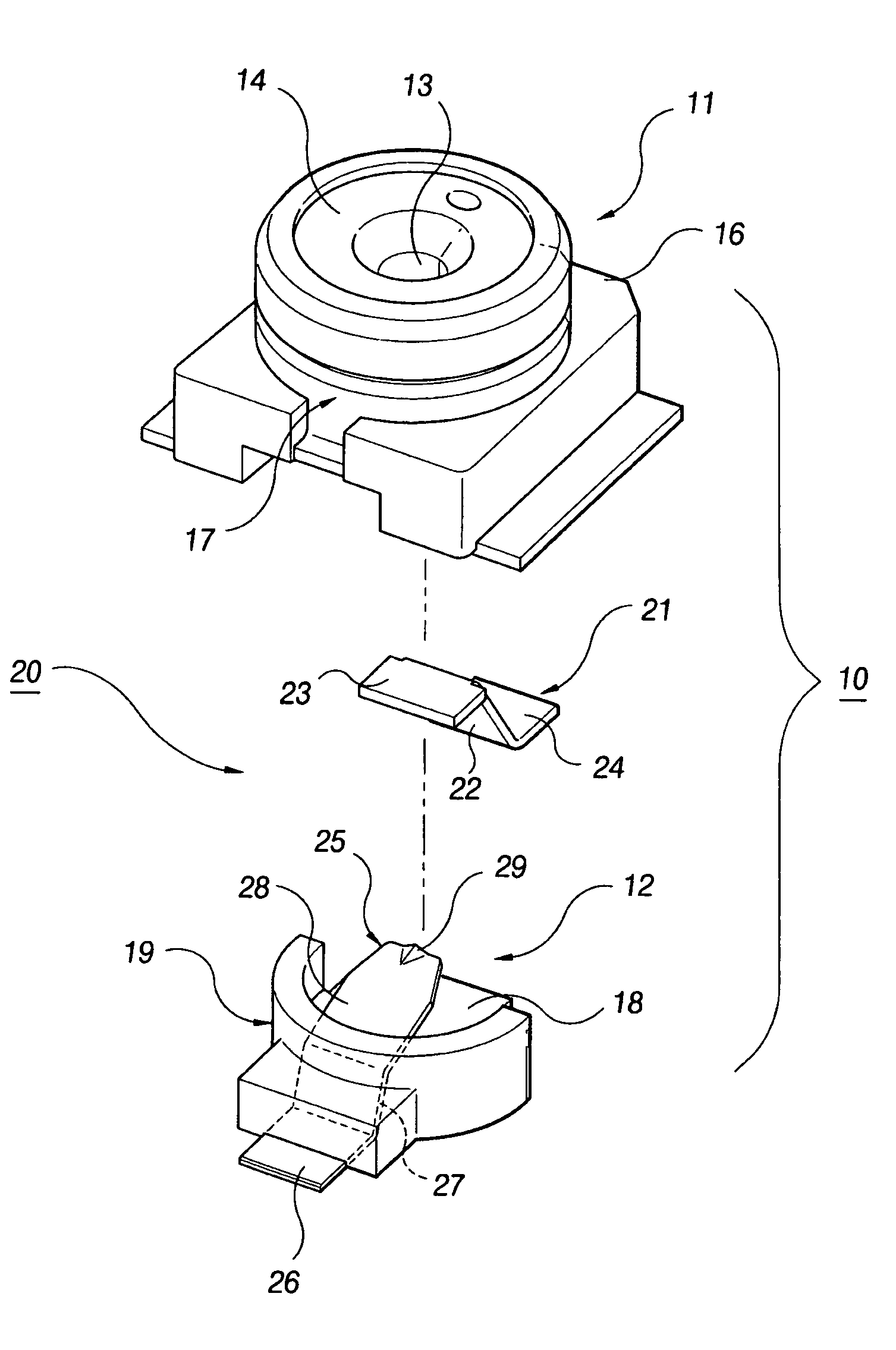
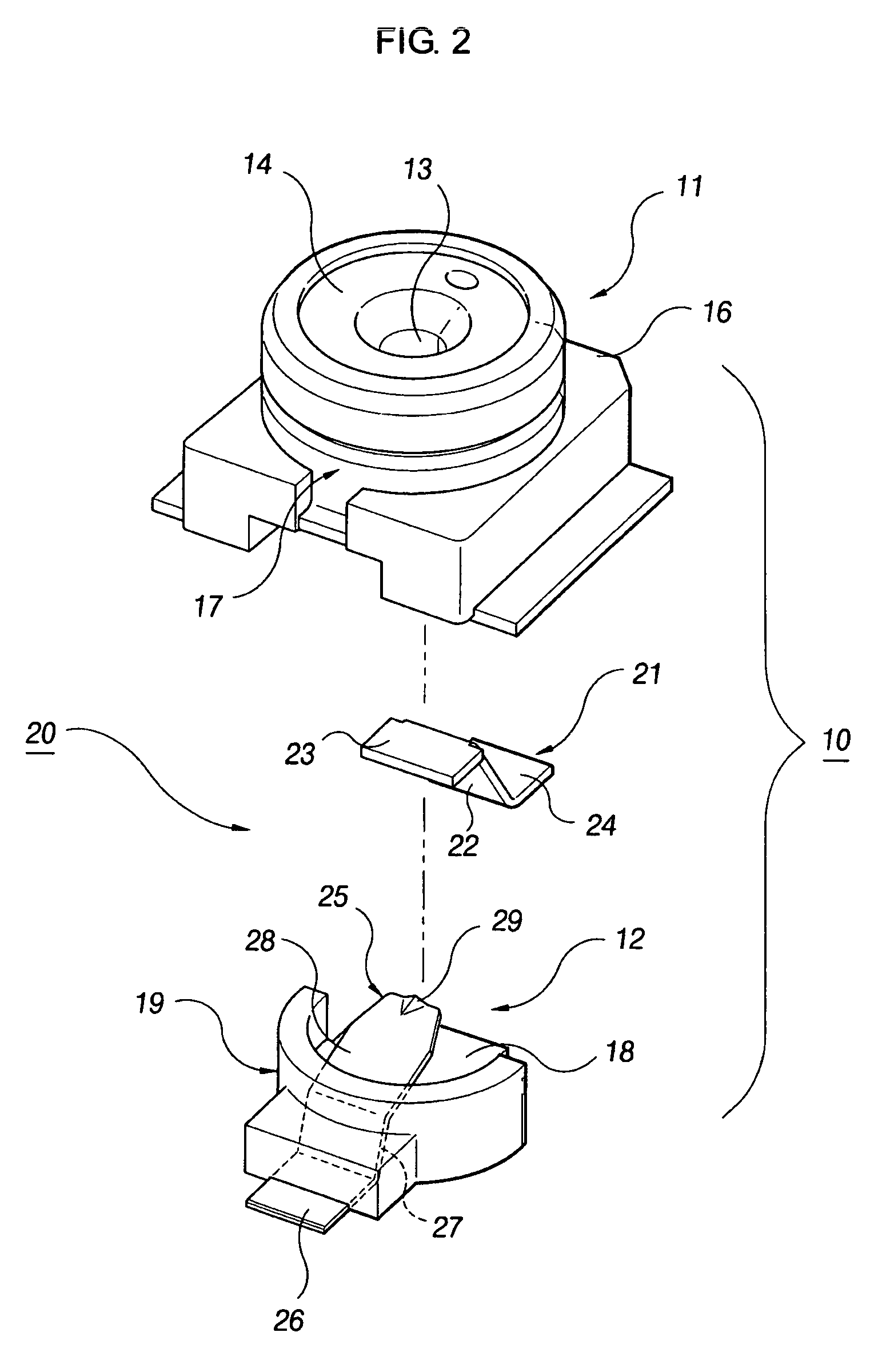
[0022]FIG. 2 is an exploded perspective view of a coaxial connector according to the present invention, and FIG. 3 is a sectional view showing an engagement state of the coaxial connector according to the present invention. As shown in these figure, the coaxial connector of the present invention comprises a housing 10, an external conductor 17 covered around the outside of the housing 10, and a switching mechanism 20 for switching an RF signal circuit installed on a circuit board of a communication device such as a mobile phone.

[0023]The housing 10 is composed of upper and lower housings 11 and 12 which are assembled with each other and generally shaped as a cylinder. As shown in FIGS. 2 to 4, the upper housing 11 comprises an upper insulating body 14 and a skirt portion 16. Here, a hole 13 into which a central co...


PUM


Abstract

The present invention relates to coaxial connector with an RF switch. In particular, a housing 10 covered with an external conductor 17 is composed of upper and lower housings 11 and 12. A fixed terminal 21 connected to an RF circuit is insert molded in the upper housing 11, and a movable terminal 25 that is selectively brought into contact with the fixed terminal 21 is insert molded in the lower housing 12. The movable terminal 25 comprises a fixed portion 26 fixed to the lower housing 12; a waist portion 27 extending upwardly from the fixed portion 26 at a first angle α1 and molded to the lower housing 12; and an elastic piece 28 bent from the tip end of the waist portion 27 at a second angle α2, extending into a space 15 of the housing, and being contact with the fixed terminal 21.

Description

CROSS-REFERENCE TO RELATED APPLICATION(S)[0001]This application claims the priority of Korean Patent Application No. 10-2004-54867, in the Korean Intellectual Property Office, the disclosure of which is incorporated herein in its entirety by reference.BACKGROUND OF THE INVENTION[0002]1. Field of Invention[0003]The present invention relates to a coaxial connector, and more particularly, to a coaxial connector which is mounted on a circuit board of a mobile communication device such as a mobile phone and is provided with a switch for interrupting an RF circuit when a central conductor of a plug connector is assembled.[0004]2. Description of the Prior Art[0005]In general, a coaxial connector with an RF switch for checking high frequency circuits is employed in portable communication equipment such as mobile phones. An example of a coaxial connector with such an RF switch is disclosed in Japanese Laid-Open Publication No. 2003-123915.[0006]As shown in FIG. 1, the conventional coaxial co...

Claims


Application Information

Patent Timeline
IPC IPC(8): H01R12/00
CPCH01R24/46H01R24/50H01R2103/00H01R13/646
Inventor YEO, WOON CHUL
Owner HECTO
Learn More