Shunt

Inactive Publication Date: 2005-08-23
COWAN JOHN A +3
View PDF18 Cites 66 Cited by
  • Summary
  • Abstract
  • Description
  • Claims
  • Application Information

AI Technical Summary

Benefits of technology

[0007]It is therefore an object of the present invention to provide a CSF shunt

Problems solved by technology

The major complications from these and other prior art shunts include infection, obstruction, disconnection, under draining, and over draining, all of which can lead to serious injury and even death.
As k

Method used


Image

  • Shunt
  • Shunt
  • Shunt

Examples


Embodiment Construction

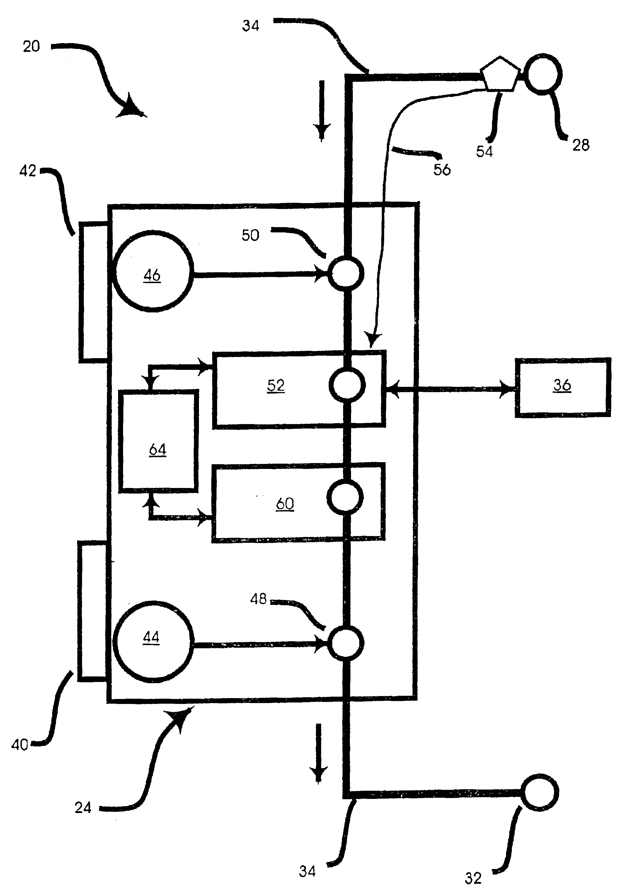
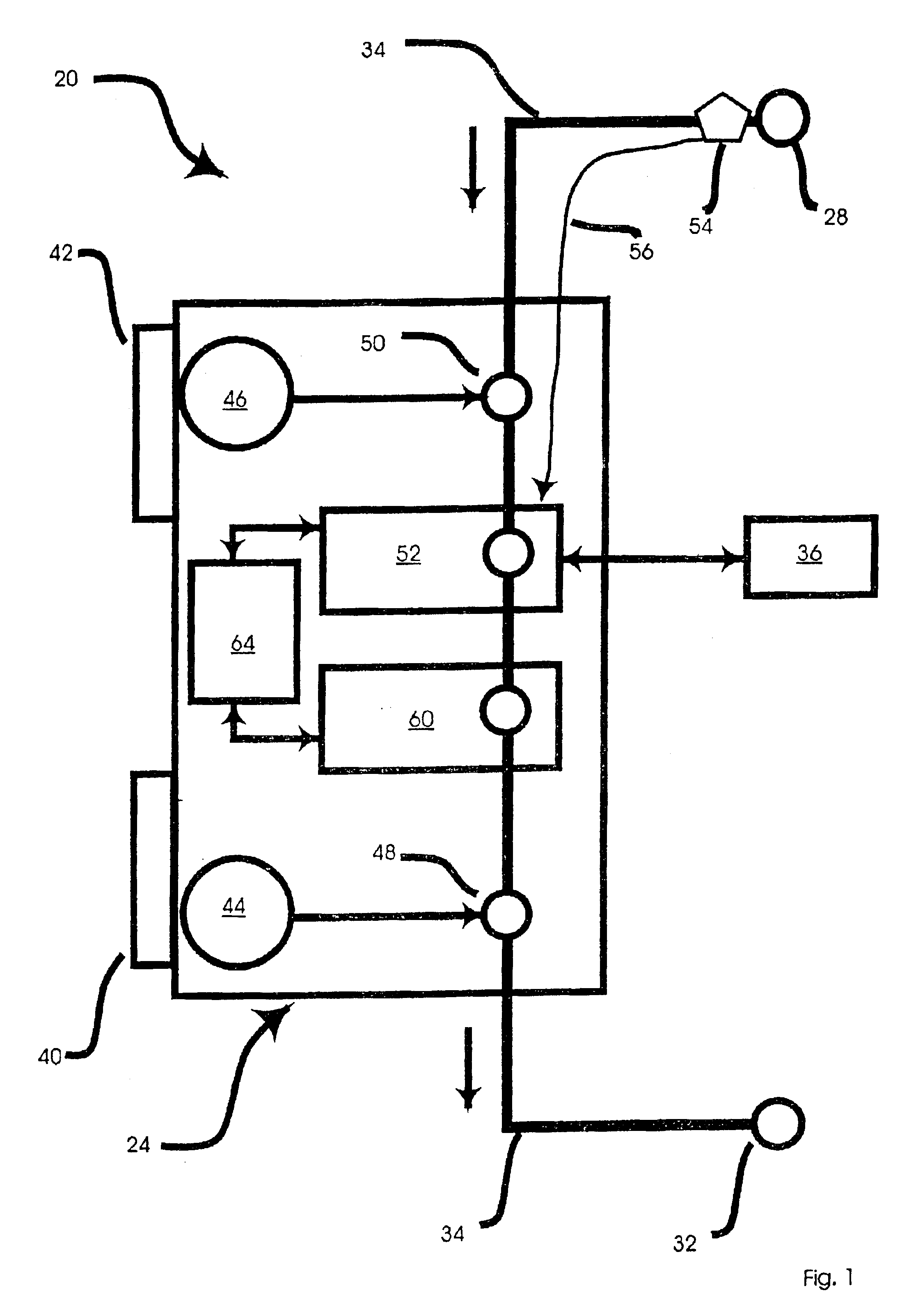
[0032]Referring now to FIG. 1, a schematic representation of a CSF shunt is indicated generally at 20. Shunt 20 comprises a master control unit 24 (which can also be referred to as the active component) that interconnects a first catheter 28, and a second catheter 32 via a catheter line 34. Master control unit 24 is preferably minitiarized and made of a biocompatible material such that it can be safely inserted in the patient's abdomen, either intra-peritoneal or extra-peritoneal, using a standard abdominal incision, and remain therein as needed to drain CSF.

[0033]After master control unit 24 is inserted into the patient's abdomen, first catheter 28 can then be tunneled from the abdomen rostrally (or caudaly) into a CSF space in the scalp to serve as an inlet for excess CSF, which in a present embodiment is a ventricle. (As used herein, the term CSF space includes any space in the body that can generate an excess of CSF requiring drainage.) A small incision in the scalp can then be ...


PUM


Abstract

A shunt for draining cerebral spinal fluid from the brain is provided. In an embodiment, the shunt includes a master control unit that is located in the abdomen, which interconnects a ventricular catheter and a second catheter, typically located in the peritoneal cavity. In a specific embodiment, the master control unit includes a variety of ‘smart’ features including at least one access port to allow the injection of solutions for the prevention or removal of blockages in the catheter, and/or antibiotics. The access port can have other uses, such as allowing a point of access for physical navigation of a catheter or the like within the shunt, thereby providing another option for breaking-up blockages, and/or allowing an access point for repairing the shunt's components. Additionally, the master control unit includes a diagnostic unit that transmits, either wirelessly or through a wired connection via the access port, diagnostic information about the status of the patient and/or the shunt.

Description

PRIORITY CLAIM[0001]This is a continuation of Application Ser. No. 09 / 942,223, filed Aug. 29, 2001, now U.S. Pat. No. 6,585,677, issued Jul. 1, 2003, the contents of which are incorporated herein by reference.[0002]The present application claims priority from U.S. Provisional Patent Application No. 60 / 228,937 filed Aug. 30, 2000, the contents of which are incorporated herein by reference.FIELD OF THE INVENTION[0003]The present invention relates generally to apparatuses for the treatment of hydrocephalus or the like, and more particularly relates to cerebrospinal fluid (“CSF”) shunts.BACKGROUND OF THE INVENTION[0004]CSF shunts are well known and used broadly to treat patients with chronic hydrocephalus. In simple terms, such shunts typically have an inlet located in the patient's brain, and an outlet into some portion of the body which can accept and expel the excess fluid. A detailed discussion of prior art CSF shunts can be found in Drake et al, The Shunt Book, © 1995 Blackwell Sci...

Claims


Application Information

Patent Timeline
IPC IPC(8): A61M27/00A61M39/02A61M39/04A61M1/10A61M25/00A61M39/00
CPCA61M27/006A61M27/002A61M39/04A61M2025/0019A61M2205/8206
Inventor COWAN, JOHN A.MURPHY, KIERANWILLIAMS, MICHAELRIGAMONTI, DANIELE
Owner COWAN JOHN A
Why Eureka
Try Eureka