Solid-state image pickup device
- Summary
- Abstract
- Description
- Claims
- Application Information
AI Technical Summary
Benefits of technology
Problems solved by technology
Method used
Image
Examples
first embodiment
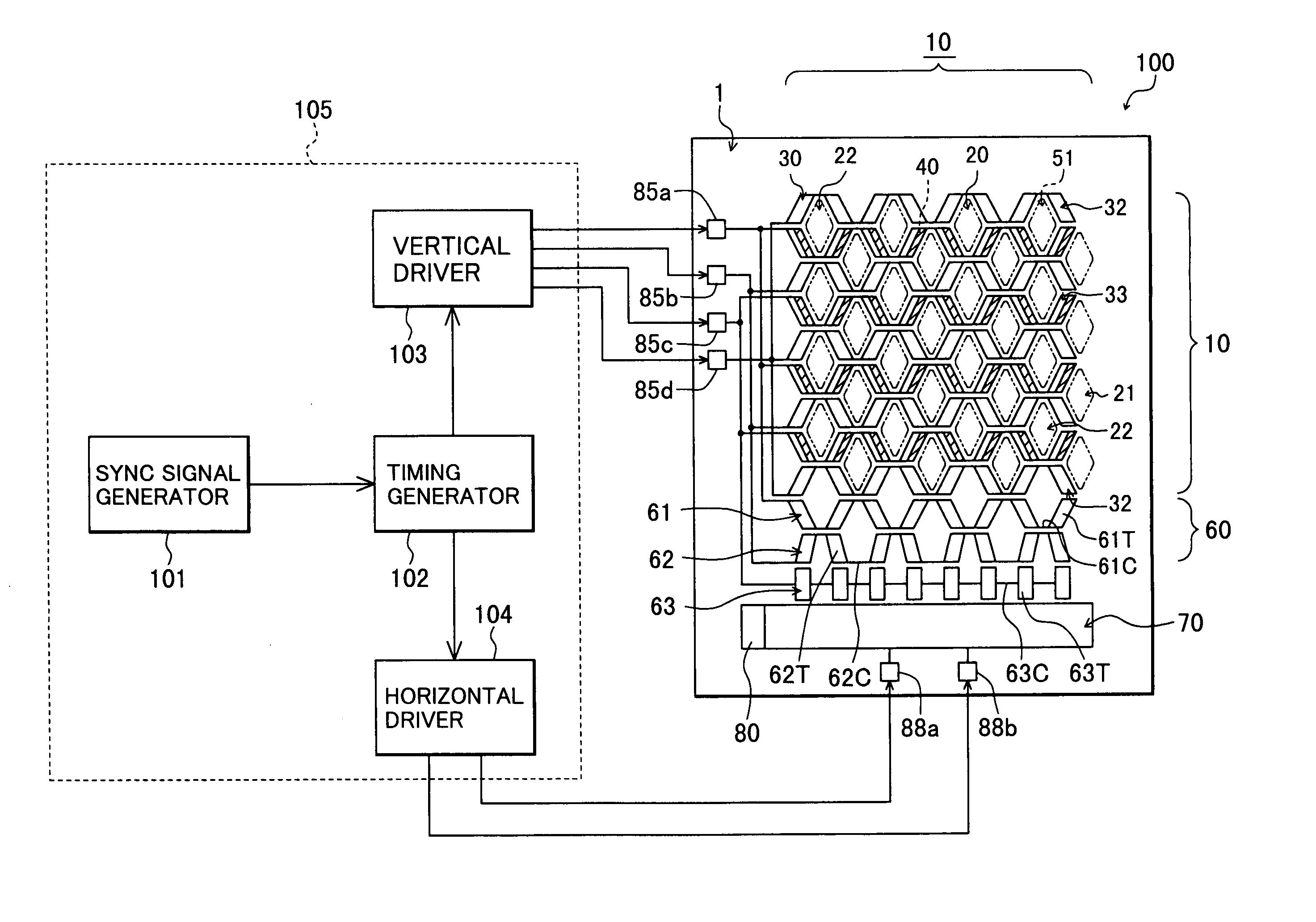
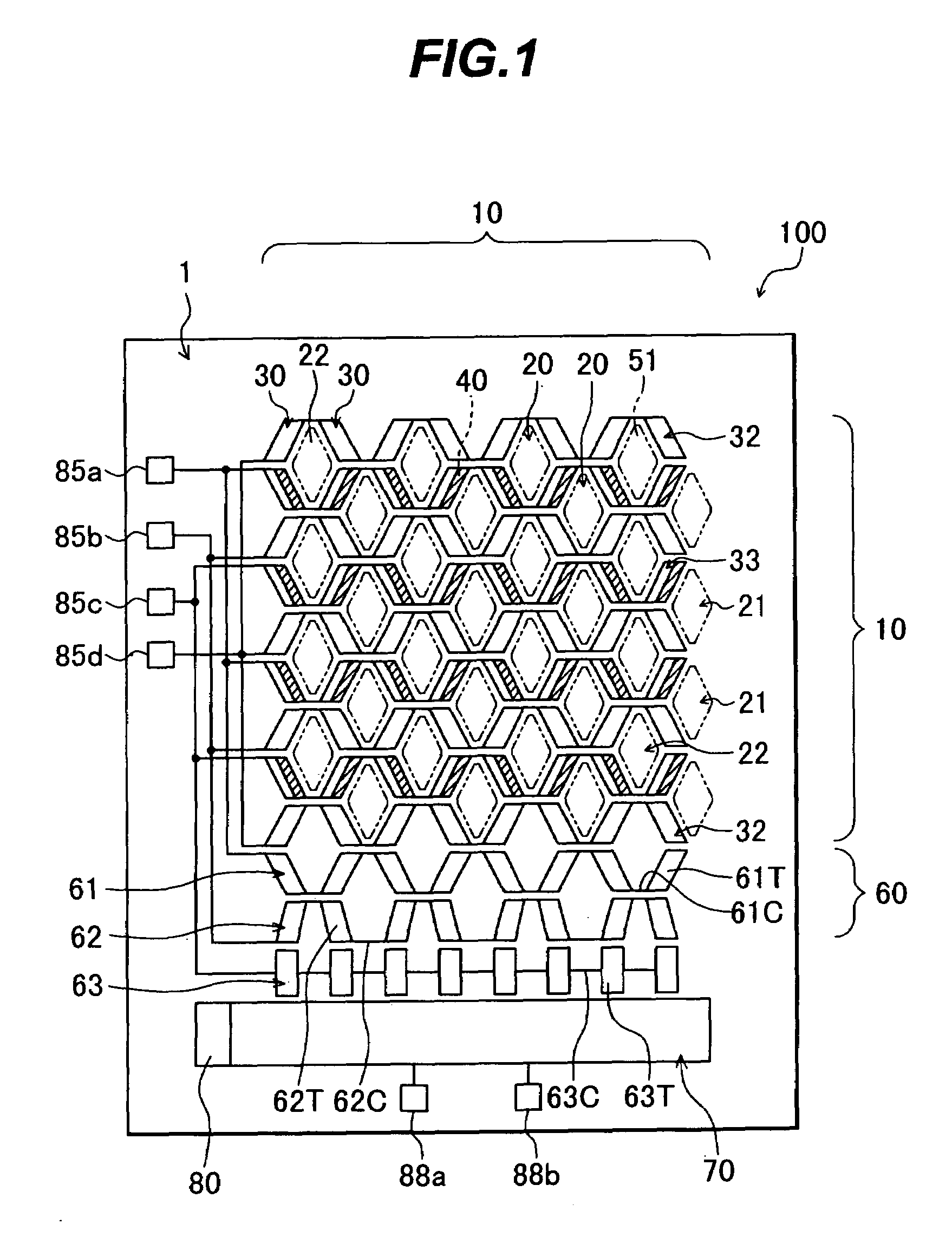
[0109]FIG. 1 schematically shows in plan view an IT-CCD 100 of a The IT-CCD 100 is an IT-CCD of interlace driving type including a plurality of pixels in a shifted-pixel layout.
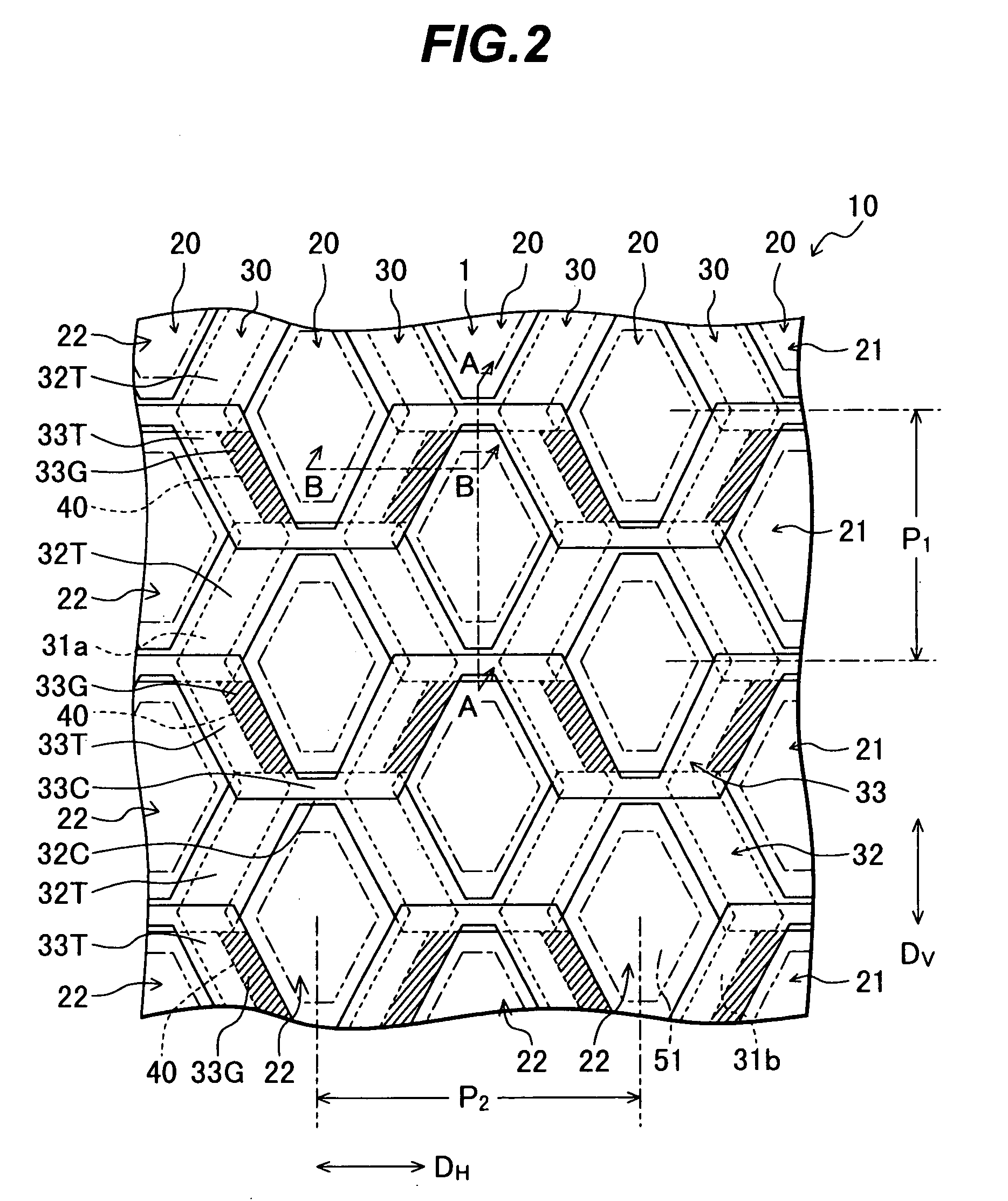
[0110]In this configuration, 32 photoelectric converters 22 in a simplified image are arranged in eight rows and in eight columns in a shifted-pixel layout. An odd photoelectric converter column 20 includes only photoelectric converters of odd rows and an even photoelectric converter column 20 includes only photoelectric converters of even rows.
[0111]An actual IT-CCD includes about several hundreds of thousand pixels to several million pixels. In such a configuration, the pixels are arranged in a shifted-pixel layout such that an odd photoelectric converter column 20 includes only photoelectric converters of odd rows and an even photoelectric converter column 20 includes only photoelectric converters of even rows. If a first photoelectric converter column 20 relative to a left-most end of the device shown in...
second embodiment
[0230]By disposing a color filter array in the IT-CCD 120, an IT-CCD for color images can be implemented. The color filter array can be produced in a procedure similar, for example, to the procedure to dispose the color filter array in the IT-CCD 110 of the
[0231]When the IT-CCD 120 is modified to produce color images, color shading seldom occurs for substantially the same reason as for the IT-CCD 110 of the second embodiment.
[0232]The IT-CCD 120 can be driven, like the IT-CCD 100, by interlaced driving. In the driving, a vertical pulse signal Va is applied to the pulse supply terminals 85a1 and 85a2 and a vertical pulse signal Vb is delivered to the pulse supply terminal 85b. Vertical pulse signal Vc is applied to the pulse supply terminals 85c1 and 85c2 and a vertical pulse signal Vd is fed to the pulse supply terminal 85d. A horizontal pulse signal Ha is applied to the pulse supply terminal 88a and a horizontal pulse signal Hb is fed to the pulse supply terminal 88b.
[0233]As a re...
fourth embodiment
[0248]Referring next to FIG. 13, description will be given of an IT-CCD of a
[0249]FIG. 13 is a plan view schematically showing an IT-CCD 130 of the fourth embodiment.
[0250]The IT-CCD 130 has the same constitution as that of the IT-CCD 120 excepting (i) the number of pulse supply terminals to supply predetermined driving pulses to each of the transfer electrodes 32, 33, 61, 62, and 63 and (ii) specifications of connections between the pulse supply terminals and the transfer electrodes 32, 33, 61, 62, and 63. In FIG. 13, the same constituent elements as those shown in FIG. 12 are assigned with the same reference numerals and duplicated description thereof will be avoided.
[0251]As shown in FIG. 13, the IT-CCD 130 includes eight pulse supply terminals 86a to 86h to supply predetermined driving pulses to the transfer electrodes 32, 33, 61, 62, and 63.
[0252]Each of the pulse supply terminals 86a to 86h is electrically connected to the predetermined transfer electrode 32, 33, 61, 62, or 63...
PUM
 Abstract
Description
Claims
Application Information
 - R&D
- Intellectual Property
- Life Sciences
- Materials
- Tech Scout
- Unparalleled Data Quality
- Higher Quality Content
- 60% Fewer Hallucinations
Browse by: Latest US Patents, China's latest patents, Technical Efficacy Thesaurus, Application Domain, Technology Topic, Popular Technical Reports.
© 2025 PatSnap. All rights reserved.Legal|Privacy policy|Modern Slavery Act Transparency Statement|Sitemap|About US| Contact US: help@patsnap.com


