Focus detecting device with photoelectric conversion portion having microlens and with light blocking portion having first and second openings

a technology of microlenses and detecting devices, which is applied in the direction of distance measurement, exposure control, instruments, etc., can solve the problems of detecting a large-defocus condition, affecting the detection accuracy of the microlense, and affecting the quality of the microlenses

Inactive Publication Date: 2005-08-23
CANON KK
View PDF55 Cites 123 Cited by
  • Summary
  • Abstract
  • Description
  • Claims
  • Application Information

AI Technical Summary

Problems solved by technology

However, the defocused condition creates a problem in that, since the configuration of the pupil divided is superimposed on a blurred image, difficulty is encountered in detecting a large-defocus condition.
In addition, in this mode, as another factor to increase the detection error on the defocus quantity, there is an error resulting from manufacturing of the microlens.
However, the microlens has a very fine structure; therefore, in fact, the difference among the microlenses stemming from the manufacturing may be compromised to some degree.

Method used


Image

  • Focus detecting device with photoelectric conversion portion having microlens and with light blocking portion having first and second openings
  • Focus detecting device with photoelectric conversion portion having microlens and with light blocking portion having first and second openings
  • Focus detecting device with photoelectric conversion portion having microlens and with light blocking portion having first and second openings

Examples


first embodiment

[First Embodiment]

[0059]First of all, a description will be given hereinbelow of an image pickup optical system for use in a first embodiment of the invention.

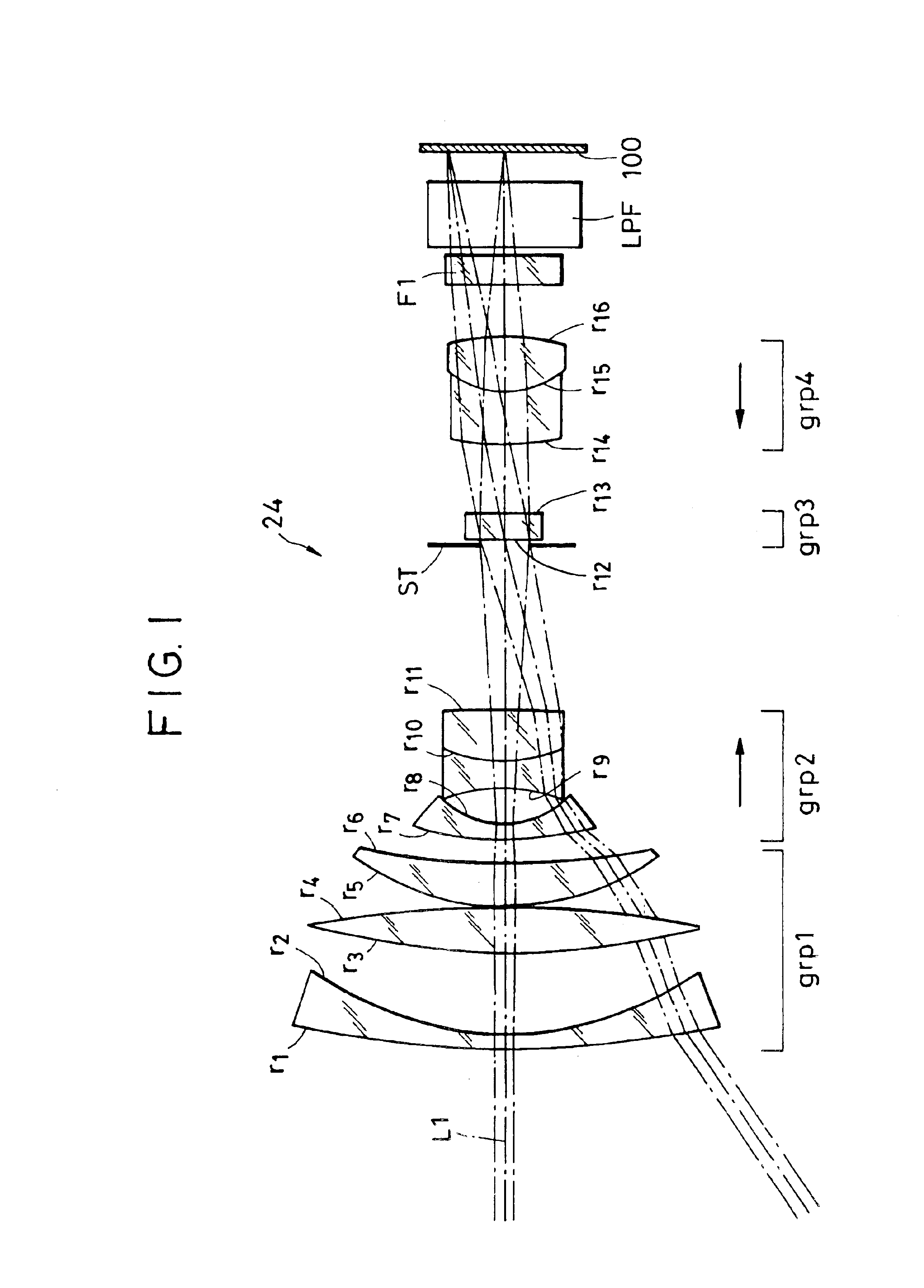
[0060]FIG. 1 is an illustration of a construction of an image pickup optical system according to the invention, showing a zoom optical system of a digital color camera using a solid-state image pickup element. In this illustration, the left side shows a subject side while the right side illustrates an image plane side.

[0061]In the illustration, the image pickup optical system, designated generally at reference numeral 24, is made up of a positive first group (grp1) comprising a negative lens having lens surfaces r1 and r2, a positive lens having lens surfaces r3 and r4 and a positive lens having lens surfaces r5 and r6, a negative second group (grp2) comprising negative and positive lenses having lens surfaces r9, r10 and r11, a diaphragm ST, a positive third group (grp3) comprising a positive lens having lens surfaces r12 and...

second embodiment

[Second Embodiment]

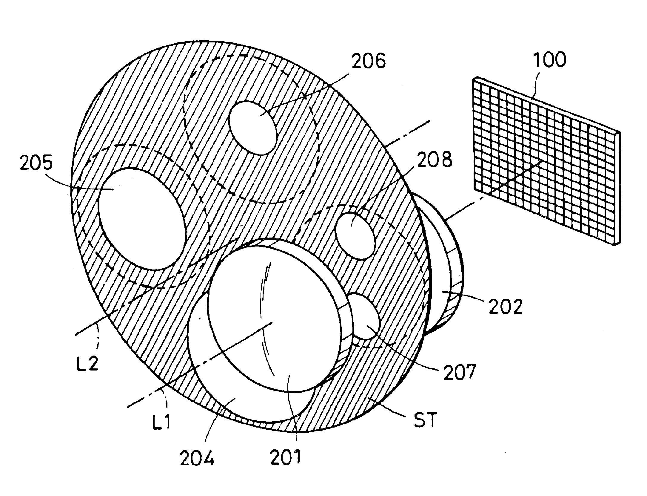
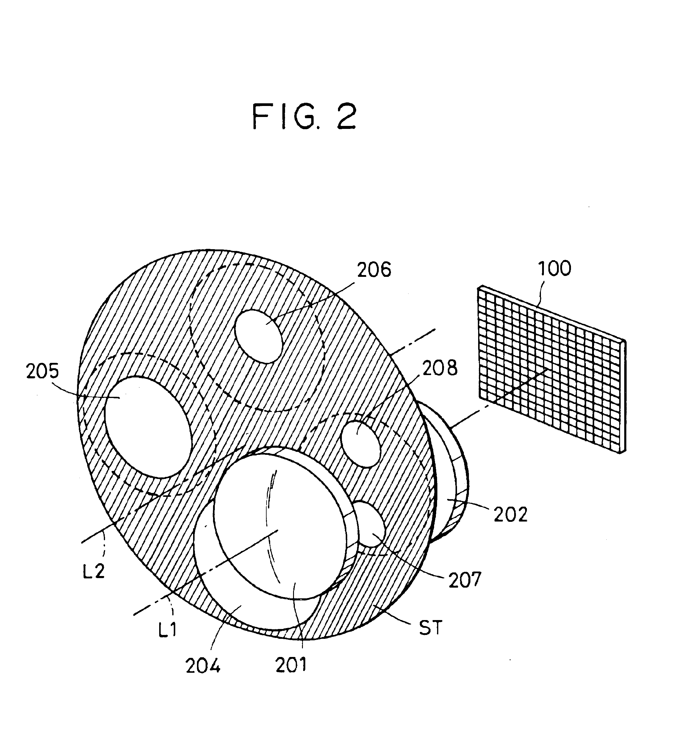
[0175]FIG. 30 shows an image pickup unit according to a second embodiment of the present invention. In the illustration, reference mark ST1 represents a first diaphragm and reference mark ST2 designates a second diaphragm rotatable coaxially with the first diaphragm ST1. The first diaphragm ST1 excludes the large-defocus detection openings 207 and 208 from the diaphragm ST according to the first embodiment shown in FIG. 28. The first and second diaphragms ST1 and ST2 are disposed in a state adjacent to each other. The first and second diaphragms ST1 and ST2 are driven by a motor (not shown) to take three or four positions.

[0176]In FIG. 30, numeral 201 designates, of an image pickup optical system 24, a front lens group collectively representing a first group (grp1) and a second group (grp2) existing on the object side with respect to the diaphragms ST1 and ST2, numeral 202 represents, of the image pickup optical system 24, a rear lens group collectively representi...


PUM


Abstract

A focus detecting device comprises a first photoelectric conversion section for performing photoelectric conversion of a light beam emitted from a first pupil area of a image pickup optical unit, a second photoelectric conversion section for performing photoelectric conversion of a light beam emitted from a second pupil area different from the first pupil area, a light intercepting section having openings for allowing passage of a portion of light in the first pupil area and for allowing passage of a portion of light in the second pupil area, and a detecting section for detecting a focus condition of the image pickup optical unit on the basis of photoelectric conversion outputs of the first photoelectric conversion means and the second photoelectric conversion sections. For example, when the image pickup optical unit has a large defocus quantity, the light intercepting section is set in an optical path for focus detection.

Description

BACKGROUND OF THE INVENTION[0001]1. Field of the Invention[0002]The present invention relates to improvement of a focus detecting device for use in film cameras, digital color cameras and other cameras, and further to improvement of an image pickup (imaging) unit internally including the same focus detecting device.[0003]2. Description of the Related Art[0004]In digital color cameras, in response to depression of a release button, a solid-state image pickup element such as a CCD or a CMOS sensor is exposed to a field image for a desired period of time, and an image signal representative of a still image in one image plane is converted into a digital signal and is subjected to predetermined image signal processing such as YC processing to obtain an image signal of a predetermined format.[0005]The digital image signal indicative of the image picked up is recorded in a semiconductor memory according to frame image. The image signal recorded is, as occasion calls, read out to be display...

Claims


Application Information

Patent Timeline
Patent Type & Authority Patents(United States)
IPC IPC(8): G02B27/10G02B7/34G02B7/28G03B13/36H04N5/232G01C3/06
CPCG02B7/34H04N5/23212H04N5/3532H04N5/3535H04N5/3696H04N23/67H04N25/533H04N25/531H04N25/704H04N25/134
Inventor SUDA, YASUO
Owner CANON KK
Why Eureka
Try Eureka