Disk drive including a base assembly having a flex-to-board edge connector

a technology of flex-to-board edge connector and disk drive, which is applied in the direction of casing/cabinet/drawer details, casings/cabinets/drawers, instruments, etc., can solve the problems of screw b>, adversely affect the operation of the drive, and increase the possibility of hda contamination by particulates or other contaminants, so as to relieve the stress of the flex cable

Inactive Publication Date: 2005-08-23
WESTERN DIGITAL TECH INC
View PDF15 Cites 89 Cited by
  • Summary
  • Abstract
  • Description
  • Claims
  • Application Information

AI Technical Summary

Benefits of technology

[0010]The flex-to-board connector may be attached to the base by an adhesive, such as an epoxy, for example. The flex cable assembly may include a stiffener disposed against the flexible film behind the trace pads, the stiffener being configured to stiffen the connecting portion of the flexible film. The stiffener may include a prehensible feature configured to enable a human or a mechanical manipulator to selectively insert and remove the connecting portion in and from the flex-to-board connector. A protective structure may be disposed around the plurality of conductive fingers. The flex-to-board connector may also include a retention feature configured to enable the connecting portion of the flexible film to be selectively coupled and decoupled from the flex-to-board connector. Each of the conductive fingers may define a superior portion above the base and an inferior portion disposed between the base and the printed circuit board, and the inferior portion may define a radius of curvature. The superior portion of each of the conductive fingers may be configured to resiliently apply a bias force against a trace pad. The inferior portion of each of the conductive fingers may be configured to resiliently apply a bias force against a circuit board pad. The flex-to-board connector further may include at least one post to relieve a stress on the flexible film.
[0012]The flex-to-board connector may include a plurality of conductive fingers, each conductive finger being configured to electrically connect one of the trace pads to a corresponding one of a plurality of circuit board pads on the circuit board. The flex-to-board connector may be configured so as to enable the flex cable to be coupled to the flex-to-board connector in a top-down fashion. The flex-to-board connector may be attached to the base by an adhesive, such as an epoxy, for example. The flex-to-board connector may be configured to couple to a flex cable assembly that includes a stiffener disposed against the flex cable behind the trace pads, the stiffener being configured to stiffen the connecting portion of the flexible film. The stiffener may include a prehensible feature configured to enable a human or a mechanical manipulator to selectively insert and remove the connecting portion in and from the flex-to-board connector. The flex-to-board connector further may include a protective structure around the plurality of conductive fingers. The flex-to-board connector may further comprise a retention feature configured to enable the connecting portion of the flexible film to be selectively coupled and decoupled from the flex-to-board connector. Each of the conductive fingers may define a superior portion above the base and an inferior portion between the base and the printed circuit board, and the inferior portion may define a radius of curvature. The superior portion of each of the conductive fingers may be configured to resiliently apply a bias force against a trace pad. Similarly, the inferior portion of each of the conductive fingers may be configured to resiliently apply a bias force against a circuit board pad. The flex-to-board connector may further include at least one post to relieve a stress on the flex cable.

Problems solved by technology

The PCBA, however, is outside the HDA—and outside the clean environment.
One problem faced by hard disk drive designers is how best to electrically connect the HSA to the PCBA without compromising the clean environment of the HDA, and to do so in a reliable, readily manufacturable and inexpensive manner.
Another disadvantage relates to the screws 158.
Moreover, the act of driving the screws 158 generates particulates that may adversely affect the operation of the drive.
This hole in the base creates a potential leak path that increases the possibility of particulate or other contamination within the clean environment of the HDA.

Method used


Image

  • Disk drive including a base assembly having a flex-to-board edge connector
  • Disk drive including a base assembly having a flex-to-board edge connector
  • Disk drive including a base assembly having a flex-to-board edge connector

Examples


Embodiment Construction

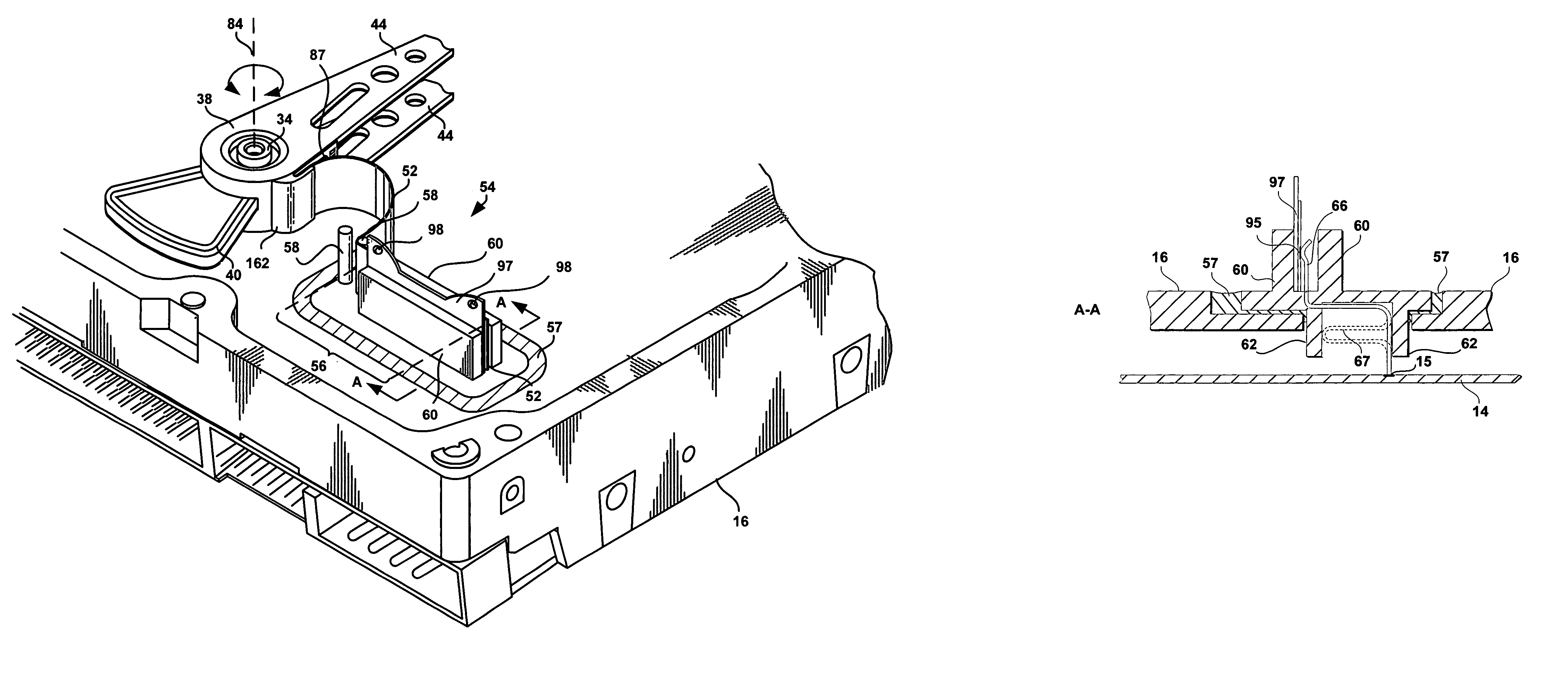
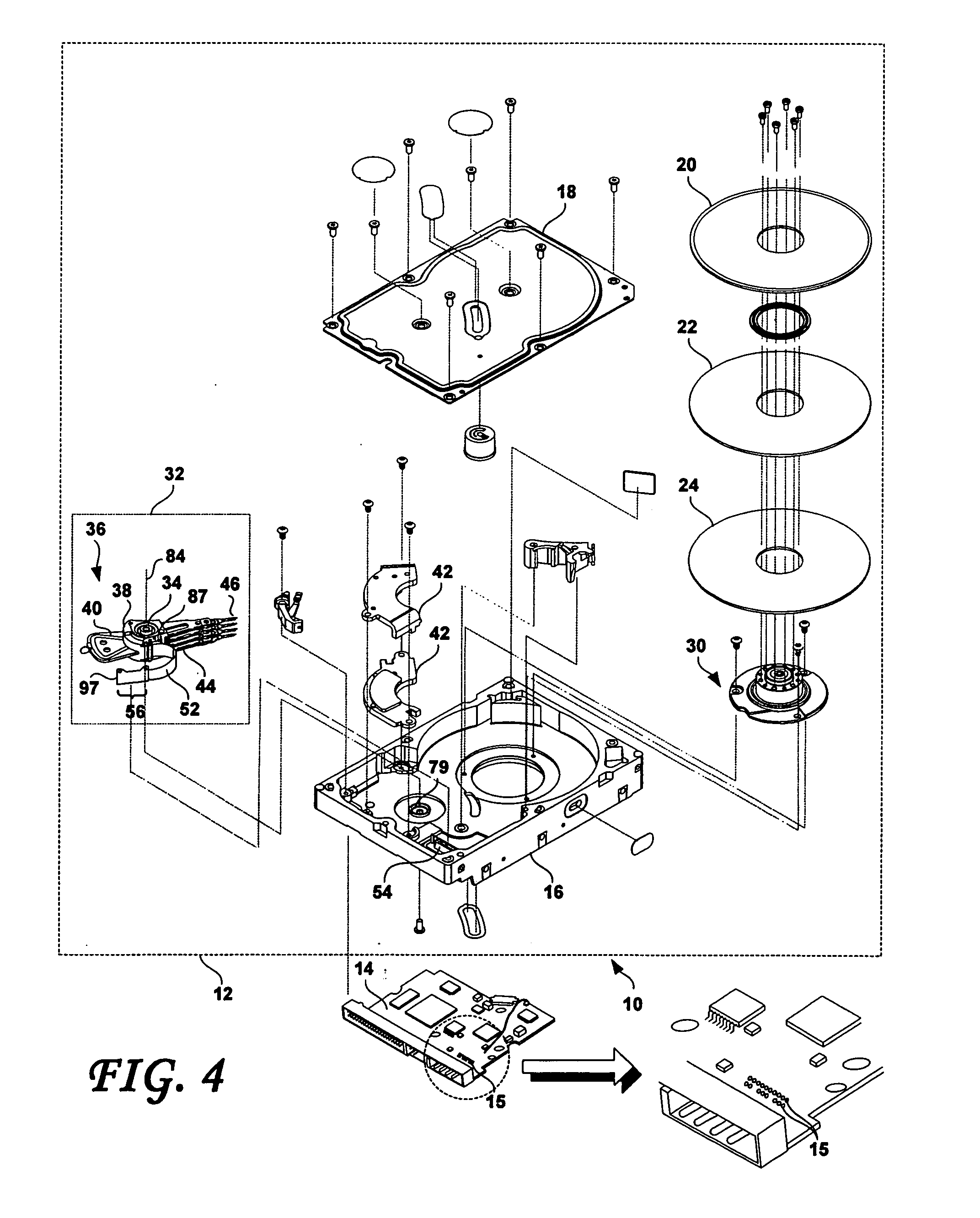
[0022]FIG. 4 is an exploded perspective view of a disk drive 10 according to an embodiment of the present invention. As shown, the disk drive 10 includes a HDA 12 and a PCBA 14. The HDA 12 includes a disk drive base 16 and a cover 18 that collectively house one or more magnetic disks, such as shown at 20, 22, 24. Each magnetic disk 20, 22, 24 contains a plurality of tracks for storing data. The head disk assembly 12 further includes a spindle motor 30 for rotating the magnetic disks 20, 22, 24. The head disk assembly 12 further includes a HSA 32 and a pivot-bearing cartridge 34. The head stack assembly 32 includes a rotary actuator 36.

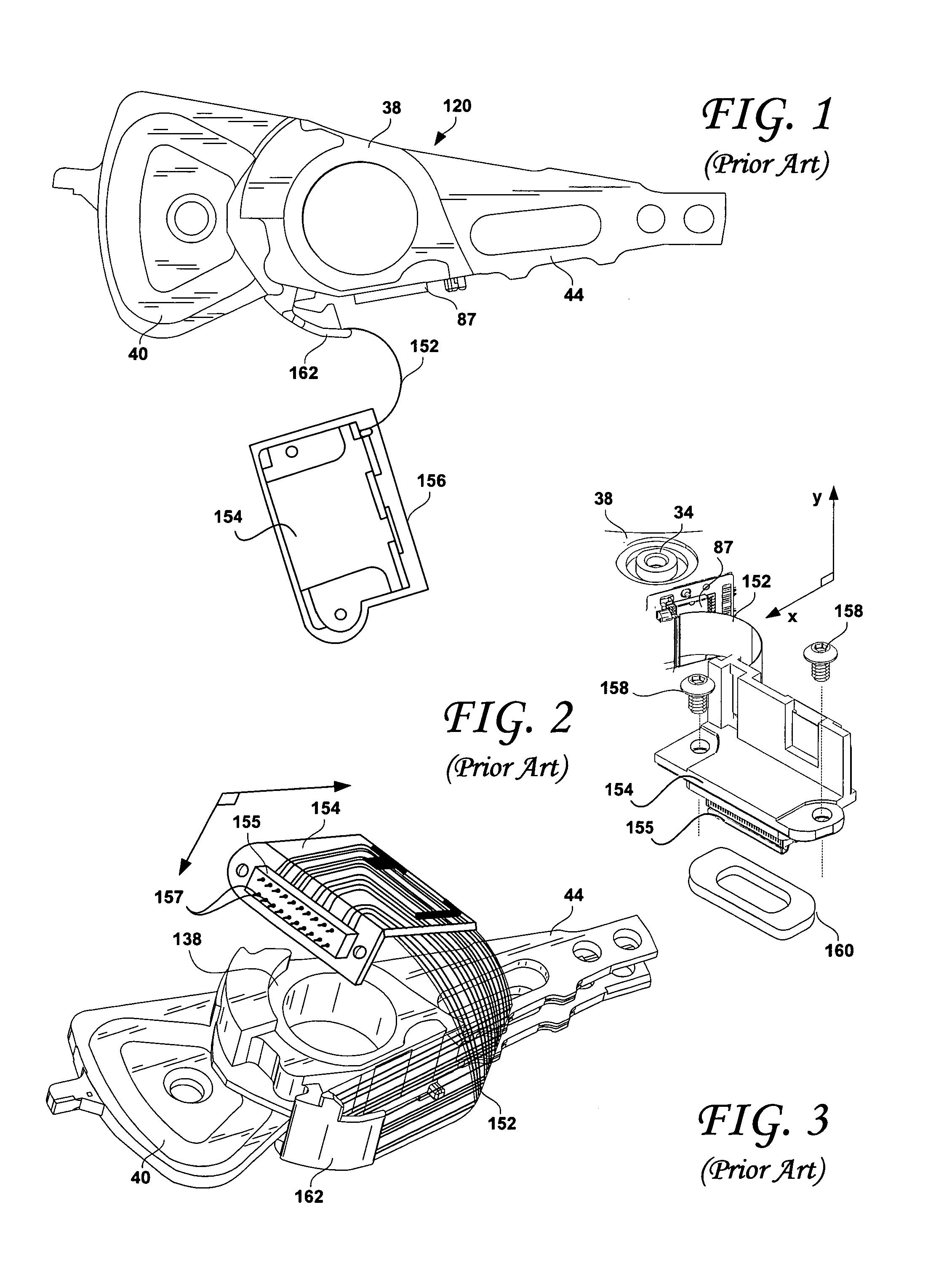
[0023]The rotary actuator 36 includes an actuator body 38 that defines a bore and a pivot-bearing cartridge 34 is engaged within the bore to pivot the rotary actuator 36 between limited positions about pivot axis 84. The rotary actuator 36 further includes a coil portion 40 that extends from one side of the actuator body 38 to interact with a pair of p...


PUM

PropertyMeasurementUnit
flexibleaaaaaaaaaa
conductiveaaaaaaaaaa
bias forceaaaaaaaaaa

Abstract

A disk drive comprises a housing including a base; a disk rotatably attached to the base; a printed circuit board coupled to the base and including a plurality of circuit board pads; a head stack assembly pivotally coupled to the base about a pivot axis and a flex-to-board connector. The head stack assembly includes a head for reading and writing to the disk and a flex cable assembly that includes a flexible film including a plurality of conductive traces that are electrically coupled to the head. The flexible film includes a connecting portion in which each of the plurality of conductive traces defines a trace pad. Each trace pad is disposed on a surface of the flexible film that is generally parallel to the pivot axis. The flex-to-board connector is attached to the base and is configured to couple to the connecting portion of the flexible film and to maintain the surface of the flexible film on which the trace pads are disposed in an orientation that is generally parallel to the pivot axis. The flex-to-board connector includes a plurality of conductive fingers, each configured to electrically connect one of the trace pads to a corresponding one of the plurality of circuit board pads.

Description

BACKGROUND OF THE INVENTION[0001]1. Field of the Invention[0002]This invention relates to magnetic disk drives. More particularly, the present invention relates to disk drives and components thereof that include a novel flex-to-board connector that electrically connects the heads of a head stack assembly with connection pads on the drive's printed circuit board assembly.[0003]2. Description of the Prior Art and Related Information[0004]Magnetic disk drives, such as those used for mass storage in personal computer systems are well known. Generally, such disk drives include a head disk assembly (HDA) and a controller printed circuit board (PCBA). The HDA includes a cover, a base, one or more disks and a head stack assembly (HSA). The HSA rotatably positions a slider (head) having one or more read and write transducers over a disk. The HSA is controllably positioned by a servo system to read or write information from or to particular tracks on the disk. The typical HSA has three primar...

Claims


Application Information

Patent Timeline
Patent Type & Authority Patents(United States)
IPC IPC(8): G11B33/12G11B5/54G11B5/48
CPCG11B5/4846G11B5/4853G11B33/121G11B33/122
Inventor BERDING, KEITH R.CASEY, SHAWN E.
Owner WESTERN DIGITAL TECH INC
Why Eureka
Try Eureka