Nanotube fiber reinforced composite materials and method of producing fiber reinforced composites

a technology of nanotubes and composite materials, applied in the field of materials science, can solve the problems of limited efforts toward realizing composite materials, difficult work, and tangled mess of carbon nanotubes, and achieve the effect of reducing the requirements for halting the deposition operation

Inactive Publication Date: 2005-08-23
AUBURN UNIV
View PDF9 Cites 293 Cited by
  • Summary
  • Abstract
  • Description
  • Claims
  • Application Information

AI Technical Summary

Benefits of technology

[0017]The present invention provides significant improvements in many aspects over the method disclosed in U.S. Pat. No. 5,936,861. For example, in one aspect, the present invention provides an effective method of generating the tool path (deposition path) along which a pre-impregnated tow is dispensed and deposited. The method minimizes the requirements for halting the deposition operation to cut off the towpreg tentatively from a dispensing nozzle and then to re-start the deposition operation at a different location.

Problems solved by technology

However, it has been found that carbon nanotubes typically tend to form a tangled mess resembling a hairball, which is difficult to work with.
This and other difficulties have limited efforts toward realizing a composite material or object containing well-dispersed nanotubes with preferred orientations.
Although some progress has been made in attempting to achieve this ability, parts produced without fiber reinforcement, or with only short fibers, typically lack adequate structural integrity for many applications.
To date, little progress has been made toward fabricating SFF parts with this high level of structural integrity.
In most cases, only composites with excessively low volume fractions of fibers are obtained using known fabrication methods and, hence, the resulting composites have exhibited low strength and stiffness, insufficient for many applications.
However, currently available SFF technologies, in their present forms, typically do not lend themselves to the production of continuous fiber composite parts.
The FDM method has been hitherto limited to low melting materials such as thermoplastics and wax and has not been practiced for preparation of metallic parts, possibly due to the difficulty in incorporating a high temperature nozzle in the FDM system.
After all layers have been completed, the part block is removed from the platform, and the excess material is removed to reveal the 3-D object This process results in large quantities of expensive prepreg materials being wasted.
In real practice, however, transferring a delicate, not fully consolidated layer from one station to another would typically tend to shift the layer position and distort the layer shape.
The removal of individual layers from their substrate also tends to inflict changes in layer shape and position with respect to a previous layer, typically leading to inaccuracy in the resulting part.
Further, the transfer apparatus may not precisely bring the object to its exact previous position.
Hence, the subsequent layer may be deposited on an incorrect spot, thereby compromising part accuracy.
The more processing stations that the growing object has to go through, the higher the chances are for the part accuracy to be lost.
Such a complex and complicated process typically makes the over-all fabrication equipment bulky, heavy, expensive, and difficult to maintain.
The equipment typically also requires attended operation, adding to expense.
For example, the hand lay-up process is labor-intensive and the quality of the resulting composite part depends highly upon the skills of an operator.
The combined process of prepreg preparation, cutting, lay-up, vacuum bagging, and autoclave or press curing is notoriously tedious, lengthy, and energy-intensive.
First, it typically requires execution of two separate processes: preform preparation and resin impregnation.
Complete impregnation of a dense or large-sized preform by a viscous resin can be very difficult.
Second, it typically requires utilization of a mold, which is normally quite costly.
Third, RTM typically is not suitable for fabricating complex-shaped parts (e.g., part with a hollow cavity).
However, filament winding generally is essentially limited to fabrication of convex-shaped hollow structures such as pressure vessels.
Unfortunately, these structures are essentially limited to be of a constant cross-section.
Both filament winding and protrusion typically are not well-suited to production of complex-shaped parts.
Although fiber placement and robotic tape-laying techniques can overcome some of the shortcomings of filament winding, they typically require the utilization of expensive, large and heavy equipment.
The fiber placing or tape laying head is typically of a complex configuration and, hence, is easily subject to malfunction.
These two techniques typically require highly specialized control software that is not usable with any other material processing machine.
In summary, currently available SFF technologies, generally speaking, do not lend themselves to the production of continuous fiber composite parts.
In general, current composite processing techniques are not capable of producing parts of a complex geometry, or producing parts of a specified geometry directly from a computer-aided design.

Method used

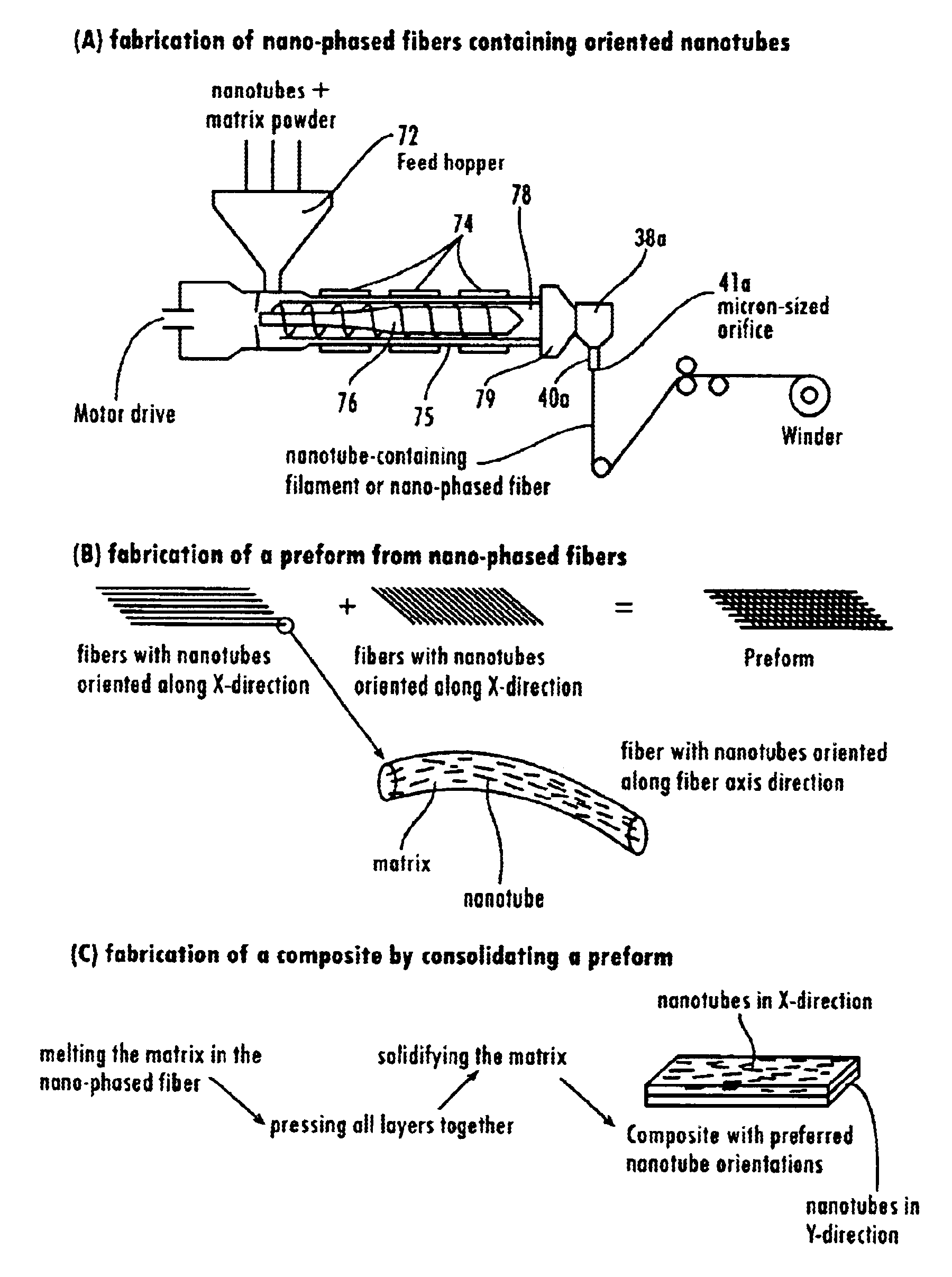
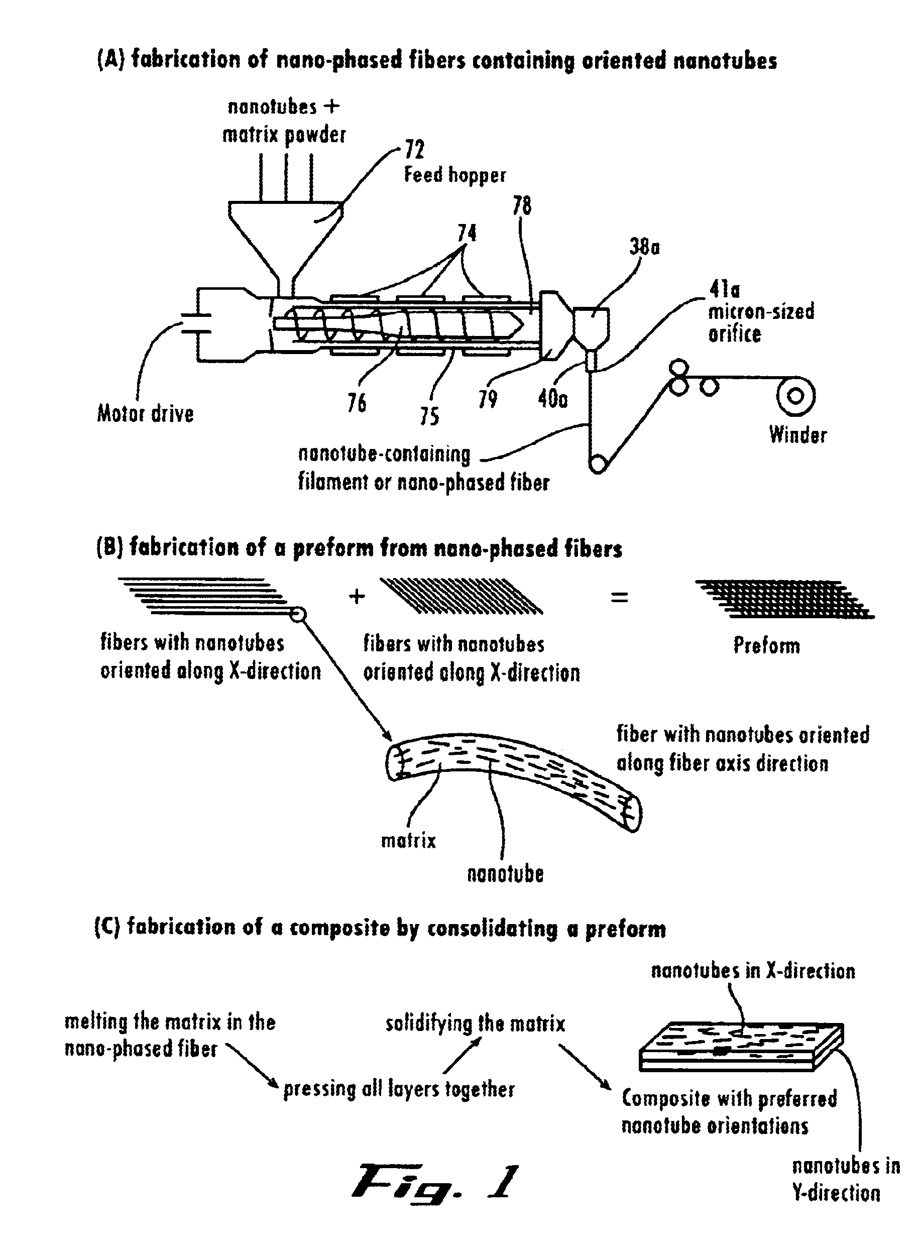

Image

  • Nanotube fiber reinforced composite materials and method of producing fiber reinforced composites
  • Nanotube fiber reinforced composite materials and method of producing fiber reinforced composites
  • Nanotube fiber reinforced composite materials and method of producing fiber reinforced composites

Examples


Embodiment Construction

[0067]The present invention may be understood more readily by reference to the following detailed description of the invention taken in connection with the accompanying drawing figures, which form a part of this disclosure. It is to be understood that this invention is not limited to the specific devices, methods, conditions or parameters described and / or shown herein, and that the terminology used herein is for the purpose of describing particular embodiments by way of example only and is not intended to be limiting of the claimed invention. Also, as used in the specification including the appended claims, the singular forms “a,”“an,” and “the” include the plural, and reference to a particular numerical value includes at least that particular value, unless the context clearly dictates otherwise. Ranges may be expressed herein as from “about” or “approximately” one particular value and / or to “about” or “approximately” another particular value. When such a range is expressed, another...


PUM

PropertyMeasurementUnit
diameteraaaaaaaaaa
angleaaaaaaaaaa
diameteraaaaaaaaaa

Abstract

A composite composition and a method of making such a composite that is composed of a matrix material and dispersed reinforcement nanotubes that are substantially aligned along at least one specified direction or axis. Also a method for making a continuous fiber-reinforced composite object by combining a reinforcement fiber tow with a solidifying matrix material to form a pre-impregnated tow or towpreg, providing a dispensing head capable of dispensing the towpreg onto a base member positioned a distance from this head with the head and base member being driven by motion devices electronically connected to a motion controller regulated by a computer, and operating and moving the head relative to the base member to dispense multiple layers of towpreg in accordance with a CAD-generated deposition path along which the dispensing head can be allowed to trace out individual layers by following a selected algorithm so that the number of path interruptions at which the towpreg must be tentatively cut off from the dispensing head is minimized.

Description

CROSS-REFERENCE TO RELATED APPLICATIONS[0001]This application claims the benefit of U.S. Provisional Patent Application Ser. No. 60 / 364,344, filed Mar. 14, 2002, and U.S. Provisional Patent Application Ser. No. 60 / 366,097, filed Mar. 20, 2002, which applications are incorporated herein by reference in their entireties for all purposes.STATEMENT REGARDING FEDERALLY-SPONSORED RESEARCH OR DEVELOPMENT[0002]The U.S. Government has a paid-up license in this invention and the right in limited circumstances to require the patent owner to license others on reasonable terms as provided for by the terms of grant number HRD-9706871 awarded by the National Science Foundation and grant number NAS9-99065 awarded by the National Aeronautics and Space Administration.FIELD OF THE INVENTION[0003]The present invention relates generally to the field of materials science, and more particularly to nanotube reinforced composite materials and methods for the production of three-dimensional objects composed ...

Claims


Application Information

Patent Timeline
Patent Type & Authority Patents(United States)
IPC IPC(8): G06F19/00C04B35/628
CPCB82Y30/00C04B35/62873C04B35/62889C04B2235/5248C04B2235/5284C04B2235/6026Y10S977/753B33Y10/00B33Y40/00B33Y30/00B33Y70/10B33Y50/02
Inventor JANG, BOR Z.LIU, JUN H.CHEN, SHIZULI, ZHIMIN M.MAHFUZ, HASSANADNAN, ASHFAQ
Owner AUBURN UNIV
Why Eureka
Try Eureka