
Waveform detection system and state-monitoring system

Inactive Publication Date: 2005-08-23
SYNCHRO
View PDF5 Cites 2 Cited by
  • Summary
  • Abstract
  • Description
  • Claims
  • Application Information

AI Technical Summary

Benefits of technology

[0127]The multiplication coefficient pattern of the present invention shown in FIG. 11 is synthesized from two elemental patterns in the procedure described below. The two elemental patterns shown in FIGS. 13A and 13B are synthesized with a time delay equal to time (=number of taps) ta to derive a differentiation characteristic pattern shown in FIG. 13C. In like manner, a pattern shown in FIG. 13D is derived with a time delay smaller than time ta. Delaying the time (=number of taps) by a certain value is equivalent to outputting data after temporarily storing in phase memory for a certain time period.

Problems solved by technology

The wavelet method is inferior to Fourier transform in terms of accuracy of spectrum analysis but it is capable of dynamic analysis.
This means that a detection delay proportional to the wavelength always exists when identifying input signal data using this type of multiplication coefficient pattern.
It is thus difficult to detect a transient decrease in this case.
The size of the scale is a major problem in analyzing non-cyclic signals with small repetitive vibrations or small-area images.
This is because the wavelet focuses on the damping curves and undulation of specified sounds, and as such, it does not effectively identify signals by sound reverberation.
When the rise and fall of an input signal have a different waveform such as shown in FIG. 42, identifying only the rising waveform is difficult, with the result that the normal waveform WA and abnormal waveform WB are not differentiated, and the system reacts strongly to the normal waveform WC.
The problem with this system is that precision operational amplifiers must be used to construct the target filters with electric elements, and the production involves very large-expenses.
However, low-pass filters (LPFs) and high-pass filters (HPFs) have a different phase gap (difference of time of change between input and output) so that it is difficult to synthesize multiplication coefficient patterns of both filters to generate a new one.
This technique involves complex procedures and huge computation overhead so that the system cost is quite high.
Furthermore, slow pulses are processed but real-time processing is impossible.

Method used


Image

  • Waveform detection system and state-monitoring system
  • Waveform detection system and state-monitoring system
  • Waveform detection system and state-monitoring system

Examples


Embodiment Construction

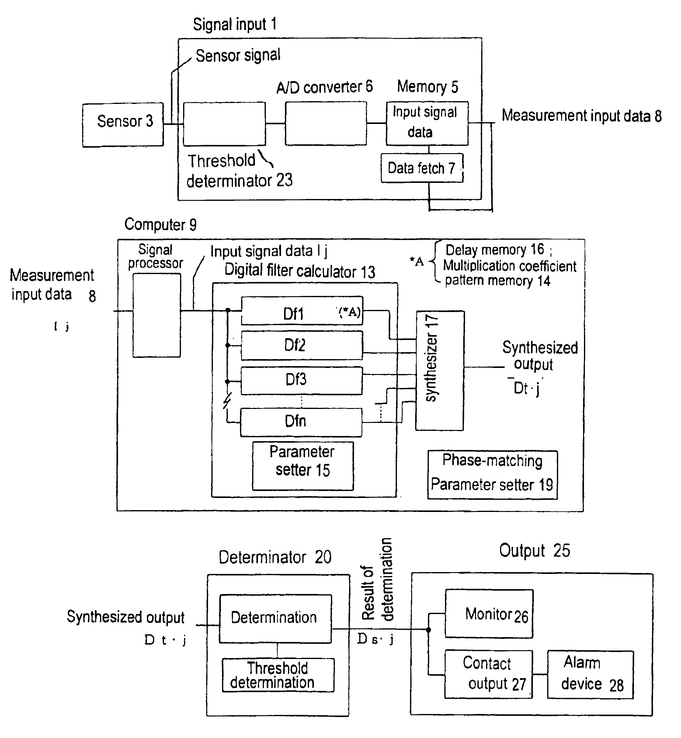
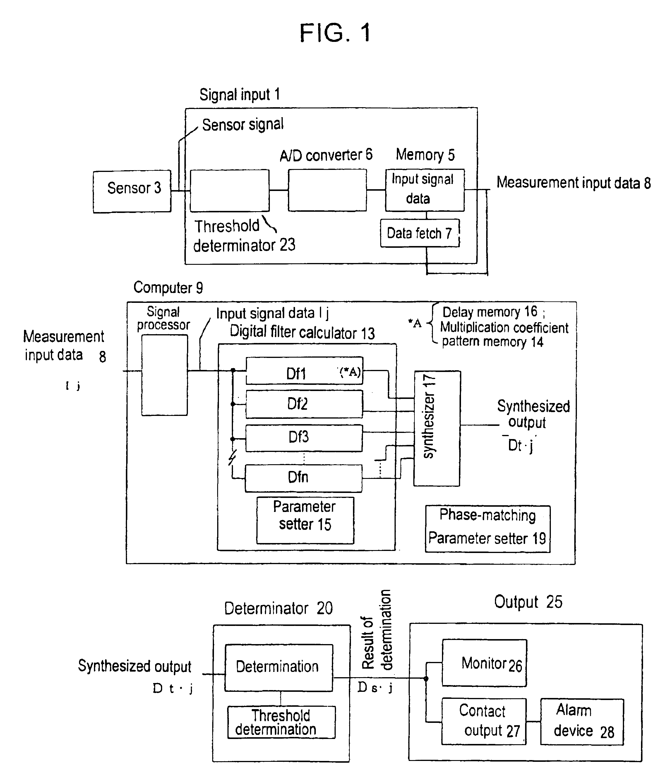
[0072]Preferred working examples of the waveform detection system with the signal processing function of the present invention and state-monitoring systems using the system are described below. FIG. 1 shows the structure of a working example of the waveform detection system. The system comprises, as shown in the figure, a sensor 3, signal input 1, computer 9, determinator 20, and output 25. These hardware components are the same as those used in the above wavelet type waveform detection system. The main structural features of the system are described below again.

[0073]The signal input 1 comprises a converter 23 that collects sensor output data, an A / D converter 4, and a memory 5. The signal input 1 converts measurement values sent from the sensor 3 into digital data. The memory 5 stores the input signals in files, and sends data as processing at the computer progresses to generate input (measurement) signal data 8 at the computer 9. The memory 5 is not essential if signals are proce...


PUM


Abstract

The present invention provides a waveform detection system and a state-monitoring system. The waveform detection system features a signal-processing function that characterizes and detects non-cyclic transient variations and performs 1 / f fluctuation conversion for input waveforms to derive output waveforms. The waveform detection system characterizes signs of state variation, incorporates multiple digital filters in the digital filter calculator of the computer, uses coefficient patterns derived from non-integer n-time integration as elemental patterns for multiplication coefficient patterns, and incorporates a manner of changing the phase of at least one of the elemental patterns, input signal data, and digital filter output so that the outputs of digital filters that use the elemental patterns are synthesized in a state where a portion of the phases of the characteristic extracting and processing function is changed. The state-monitoring system of the present invention monitors states based on the signal processing of the waveform detection system.

Description

FIELD OF THE INVENTION[0001]The present invention relates to a waveform detection system with a signal processing function that detects non-cyclic transient state variations by characterizing and generating output waveforms by 1 / f fluctuating input waveforms, and a state-monitoring system using the waveform detection system.BACKGROUND ART[0002]A wavelet method, commercialized as a result of recent developments of computer technology, is used to search for signs in time-series data in a state-monitoring system. The wavelet method is inferior to Fourier transform in terms of accuracy of spectrum analysis but it is capable of dynamic analysis. The wavelet method more accurately captures spectral changes in both time-series data and images. Currently, the wavelet method is extensively used to detect signs in time-series data and recognize images in image data.[0003]FIGS. 37 and 38 show the structure of a waveform detection system based on the existing wavelet method (hereafter called th...

Claims


Application Information

Patent Timeline
IPC IPC(8): G01R13/00G01R23/16G01R23/167H03H17/02H03H17/08
CPCG01R13/00G01R23/167
Inventor AGEISHI, YOUICHIWADA, TETSUYUKI
Owner SYNCHRO
Learn More