
Access control apparatus and method for controlling access to storage medium

a control apparatus and storage medium technology, applied in the direction of electronic editing, digital digital analogue information signals, instruments, etc., can solve the problems of long seek distance between channels, inadequacies for real time processes, and preventing real-time processes of success, so as to achieve the effect of quick reading through channels

Inactive Publication Date: 2005-08-23
FUJITSU LTD
View PDF29 Cites 18 Cited by
  • Summary
  • Abstract
  • Description
  • Claims
  • Application Information

AI Technical Summary

Benefits of technology

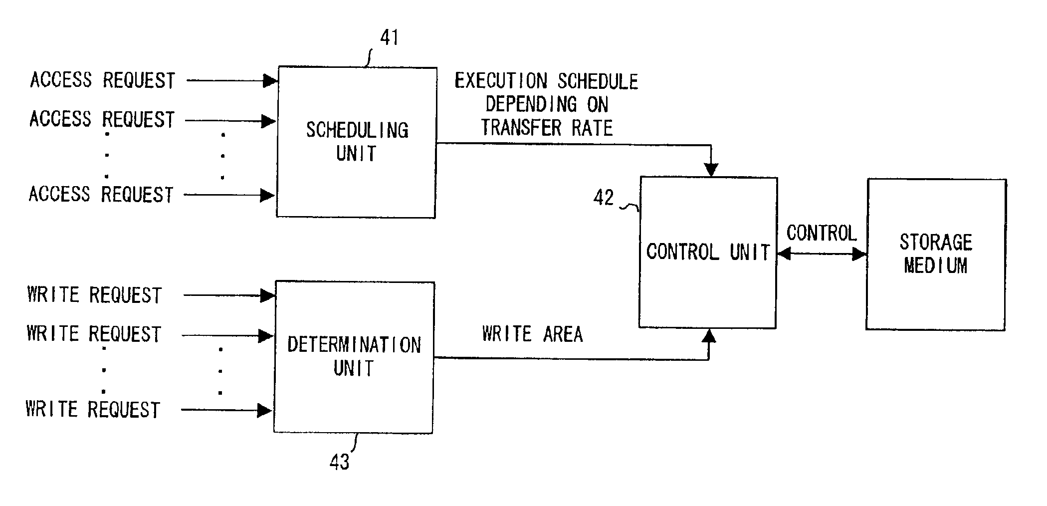
[0072]With the above mentioned access control apparatus, even when a simultaneous write request for picture data through a plurality of channels is issued, the data of the channels is sequentially and collectively written, thereby considerably reducing the wait for seek or turn when data is to be written. Therefore, the processes can be efficiently performed, and data can be recorded / read through a larger number of channels.
[0092]With the above mentioned access control apparatus, data of a specified channel can be quickly read through a channel.

Problems solved by technology

The above mentioned time factors often prevent a real time process of successfully keeping a schedule after terminating a process within a predetermined deadline.
Therefore, they are not appropriate for a real time process.
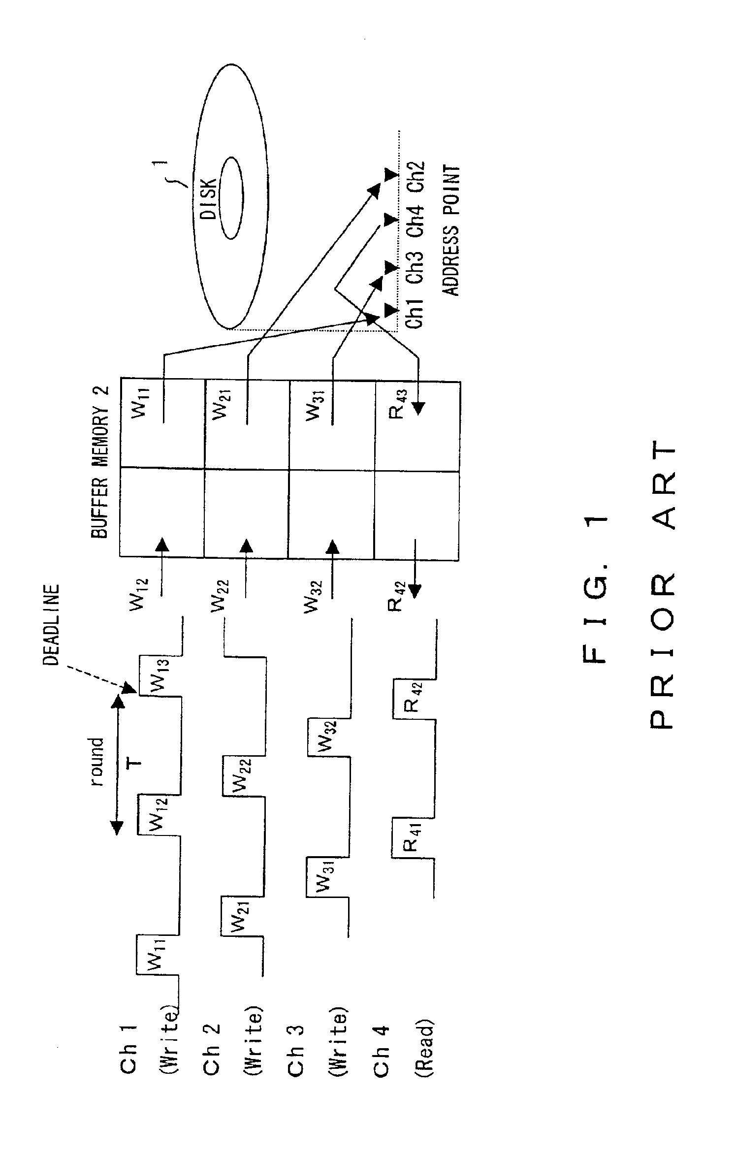
However, since the address points of the channels Ch1 through Ch4 are arranged in a different order, the seek distance between channels is long, and it takes a long time to move the head.
Therefore, there can be the possibility that an access request is not satisfied due to a long access interval.
However, the above mentioned conventional disk scheduling has the following problems.
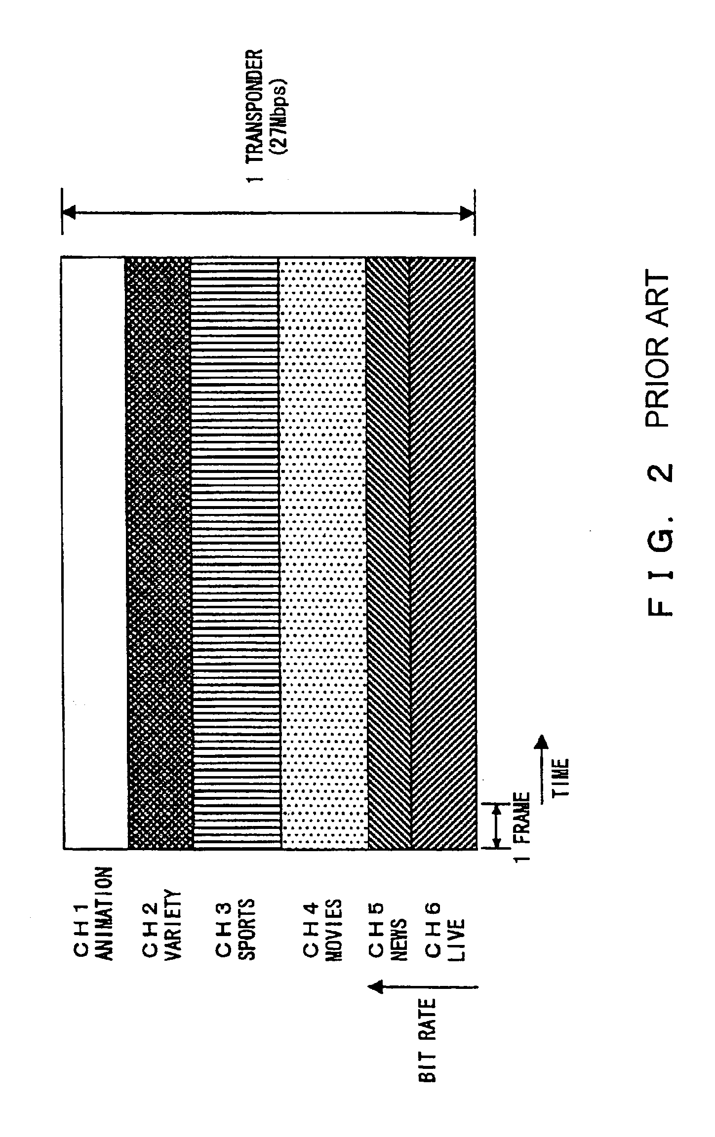
Therefore, the transfer rate is not always constant.
Therefore, data cannot be processed through a larger number of channels.
Therefore, when data is processed through a large number of channels, it may undesirably take a long seek time.
However, the conventional scheduling method does not consider the above mentioned plurality of zones, but assumes that data are uniformly stored in inner and outer zones on the disk, and the amount of data and the transfer rate are uniform in the inner and the outer zones.
Therefore, the performance becomes worse when data at a high transfer rate is collectively written to an inner zone.
Therefore, data cannot be processed through a large number of channels in this method.
When the simultaneous recording and the simultaneous reading are performed on multi-channel picture data, higher performance is required, and the data cannot be correctly processed in the inner zones.
The problem occurs in the HDD (Hard Disk Drive).
However, when access is gained for plural zones, a control time to change the number of revolutions is required, which reduces the performance.

Method used


Image

  • Access control apparatus and method for controlling access to storage medium
  • Access control apparatus and method for controlling access to storage medium
  • Access control apparatus and method for controlling access to storage medium

Examples


first embodiment

[0414]Described below first is the In this embodiment, the total storage function is obtained without the access time including the moving time (seek time) between zones, and the number of channels for the processes taken into account, the obtained function is compared with the above mentioned total request function, and a zone for use in attaining the function is selected.

[0415]As a result, the recording method in the steps 1 through 3 is determined as follows.

[0416]Step 1: The total storage function of the zones 1 and 2 is 18.75 Mbps, and is higher than the total request function of step 1. Therefore, data is distributed and recorded in the zones 1 and 2.

[0417]Step 2: The transfer rate (=17.5 Mbps) of the zone 1 is higher than the total request function in step 2. Therefore, the data is recorded in the zone 1.

[0418]Step 3: Since the total storage function of the zones 2 and 6 is 25 Mbps, and is higher than the total request function in step 3, the data is distributed and recorded...

second embodiment

[0423] described below, the total storage function is obtained with the access time including the moving time (seek time) between zones taken into account, the obtained function is compared with the total request function in each step, and a zone for realizing the function is selected. In this case,

[0424]Access time=100 ms×distance between zones

[0425]Distance between zones=difference between numbers of two selected zones

[0426]Assuming that the access time of 100 m (50 ms for one way) is required to move to an adjacent zone. The longer the distance between the zones, the longer the access time proportional to the moving distance of the head.

[0427]As a result, the recording method in each step is determined as follows.

[0428]Step 1: In response to the total request function of 18 Mbps (recording through three channels), the zones 2 and 3 whose total storage functions (=(20+22.5)×0.9 / 2) exceed the total request function including the access time (100 ms) are selected to record the block...

third embodiment

[0435]In the third embodiment described below, the total storage function is obtained with the moving time (seek time) between zones and the number of channels to be processed taken into account, the obtained function is compared with the total request function in each step, and a zone realizing the function is selected. In this embodiment, it is assumed that the data through each channel is distributed and recorded for convenience in individually reading or deleting the data.

[0436]As a result, as described below, the recording method in steps 1 through 3 is determined.

[0437]Step 1: In response to the total request function of 18 Mbps (recording through three channels), the zones 2 and 3 whose total storage functions (=(20+22.5)×0.9 / 2) exceed the total request function including the access time (100 ms) are selected to record the block data through Ch1 through Ch3 alternately in the zones 2 and 3. In this example, three channels are used, and the data through Ch1 and Ch2 is recorded...


PUM

PropertyMeasurementUnit
thicknessaaaaaaaaaa
thicknessaaaaaaaaaa
pit lengthaaaaaaaaaa

Abstract

In a write process through channels Ch1, Ch2, and Ch3, the deadline of each channel is set based on the transfer rate variable by the ratio of dummy packets to valid packets, and deadline information is written with write data on a disk. In a read process through a channel Ch4, the deadline is set according to the deadline information read with read data from the disk. Then, data is sequentially processed in order from the data having the earliest deadline. Considering the difference in transfer rate between outer and inner zones on the disk, a write zone is determined. When data is simultaneously recorded through the channels Ch1 and Ch2 on an ASMO in a groove-land record system, the data is sequentially recorded through the channel Ch1 on the groove and through the channel Ch2 on the land.

Description

CROSS REFERENCE TO RELATED APPLICATION[0001]This application is a continuation of international PCT application No. PCT / JP99 / 05679 filed on Oct. 14, 1999.BACKGROUND OF THE INVENTION[0002]1. Field of the Invention[0003]The present invention relates to an apparatus and method for controlling the access to a storage medium to simultaneously record / read data along a plurality of channels.[0004]2. Description of the Related Art[0005]With remarkable progress in moving picture coding / decoding LSI (large scale integration) for microcomputers, MPEG 2 (Moving Picture Experts Group Phase 2), etc., the technology of digitizing pictures has been outstandingly improved. As a result, television broadcasting is quickly changing from an analog system to a digital system.[0006]In satellite broadcasting using a BS (broadcasting satellite), a CS (communications satellite), etc., programs of several hundred channels are prepared in response to various requests from users.[0007]With the growing tendency ...

Claims


Application Information

Patent Timeline
Patent Type & Authority Patents(United States)
IPC IPC(8): G11B20/10G11B19/02G11B27/036G11B27/031G11B20/12G11B7/007G11B7/14H04N5/76G11B27/034G11B7/0037G11B7/00H04N9/804H04N5/765H04N5/85H04N5/84G06F3/06G11B27/10H04N21/21H04N21/23
CPCG06F3/061G06F3/0656G06F3/0674G11B7/007G11B7/00718G11B7/14G11B19/02G11B20/10G11B20/12G11B20/1217G11B27/036G11B27/105H04N5/76H04N21/21H04N21/23G11B7/0037G11B27/034G11B2020/10592G11B2020/1062G11B2020/1238G11B2220/20G11B2220/216H04N5/765H04N5/85H04N9/8042
Inventor OKADA, YOSHIYUKI
Owner FUJITSU LTD
Learn More