Injection Apparatus and Method

a technology of injection apparatus and injection chamber, which is applied in the direction of fluid removal, sealing/packing, borehole/well accessories, etc., can solve the problems of lack or poor control of what is happening downhole, and achieve the effects of reducing the wait for cement woc, reducing costs, and efficiently mixing

Inactive Publication Date: 2009-12-03
SCHLUMBERGER TECH CORP
View PDF16 Cites 13 Cited by
  • Summary
  • Abstract
  • Description
  • Claims
  • Application Information

AI Technical Summary

Benefits of technology

[0026]The invention enables reducing the wait on cement WOC during the cementing operations by directly injecting the chemical activator into the annulus around the casing whenever and wherever required. Further, the invention may also be used in other applications, such as the downhole preparation of a gelling system, based on polymers and cross-linkers. The chemical additive can be efficiently mixed with the cement slurry during the displacement process in the desired zones of interest, for example near the casing shoe. The invention enables operating the injection apparatus from the surface, by using variations of the pump flow rate, for a total control on opening and closing positions of the injection nozzles. Thus, a selective treatment of the slurry in the zones of interest, minimizing the required volume of chemical additive in the reservoir and reducing costs, is possible with the invention. It also enables using a downhole reservoir having a limited capacity and geometry adapted to the size of casing joints.
[0027]The invention enables, by reducing the WOC, keeping the rig idle as low as possible which is financially advantageous for the rig operators. Further, the invention enables reducing the risk linked with pumping the accelerator from the surface which may be problematic if the slurry sets during displacement.

Problems solved by technology

The main disadvantage of such cementing operations is the lack or poor control about what is happening downhole.

Method used


Image

  • Injection Apparatus and Method
  • Injection Apparatus and Method
  • Injection Apparatus and Method

Examples


Embodiment Construction

[0036]At the outset, it should be noted that in the development of any such actual embodiment, numerous implementation-specific decisions must be made to achieve the developer's specific goals, such as compliance with system related and business related constraints, which will vary from one implementation to another. Moreover, it will be appreciated that such a development effort might be complex and time consuming but would nevertheless be a routine undertaking for those of ordinary skill in the art having the benefit of this disclosure.

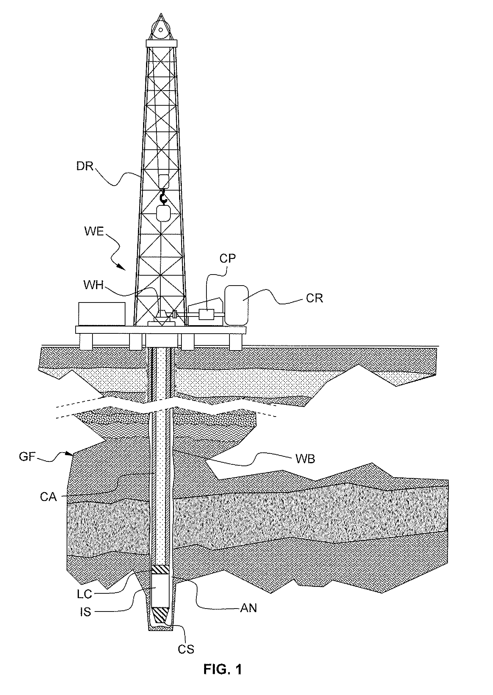
[0037]FIG. 1 schematically shows an onshore hydrocarbon well location and equipments WE above a hydrocarbon geological formation GF after drilling operation has been carried out and after a casing string CA has been run. At this stage, the well-bore WB is a bore-hole generally filled with various fluid mixtures (e.g. the drilling mud or the like). The equipment WE comprises a drilling rig DR for running the casing string CA in the bore-hole, cementi...


PUM


Abstract

The invention relates to an injection apparatus for injecting a chemical additive into a fluid mixture flowing in a well-bore. The invention also relates to a corresponding injection method. A particular application of the invention relates to the oilfield industry, for example in cementing operation

Description

CROSS-REFERENCE TO RELATED APPLICATIONS[0001]This application claims the benefit of EP Patent Application 08157376.8 filed on May 30, 2008, entitled “An Injection Apparatus and Method.”FIELD OF THE INVENTION[0002]The invention relates to an injection apparatus for injecting a chemical additive into a fluid mixture flowing in a well-bore. The invention also relates to a corresponding injection method. One particular application of the invention relates to the oilfield industry, for example in cementing operation.BACKGROUND OF THE INVENTION[0003]The statements in this section merely provide background information related to the present disclosure and may not constitute prior art.[0004]During a hydrocarbon well drilling operation and after a hydrocarbon well has been drilled, various fluid injecting operations are generally carried out. The fluid injecting operations serves various purposes, for example delivering a chemical mixture into a fluid present in the borehole for consolidatio...

Claims


Application Information

Patent Timeline
Patent Type & Authority Applications(United States)
IPC IPC(8): E21B34/10E21B34/06E21B33/13
CPCE21B27/02E21B23/006E21B33/14E21B33/13
Inventor SHINDGIKAR, NIKHILRAYSSIGUIER, CHRISTOPHE
Owner SCHLUMBERGER TECH CORP
Why Eureka
Try Eureka