Monoprolellant/hypergolic powered proportional actuator

a proportional actuator and hypergolic technology, applied in the direction of servomotors, manufacturing tools, explosives, etc., can solve the problems that the analogous procedure cannot be accomplished electrically or with any other conventional form of power control, and achieve the effect of reducing energy loss, simplifying the design of the flow control valve, and reducing the flow rate passing through the valv

Inactive Publication Date: 2005-08-30
VANDERBILT UNIV
View PDF13 Cites 6 Cited by
  • Summary
  • Abstract
  • Description
  • Claims
  • Application Information

AI Technical Summary

Benefits of technology

[0021]Unlike the combustion of hydrocarbon fuels, this approach does not require premixing, pre-compression, or an ignition system in order to generate gaseous products. Additionally, the monopropellant approach enables flow control of the liquid state rather than the gaseous state of the fuel, which greatly decreases energy loss from flow control, and greatly simplifies the design of the flow control valve (i.e., it significantly decreases the flow rate passing through the valve). The analogous procedure cannot be accomplished electrically or with any other conventional form of power control.

Problems solved by technology

The analogous procedure cannot be accomplished electrically or with any other conventional form of power control.

Method used


Image

  • Monoprolellant/hypergolic powered proportional actuator
  • Monoprolellant/hypergolic powered proportional actuator
  • Monoprolellant/hypergolic powered proportional actuator

Examples


first embodiment (

FIGS. 1A-1C)

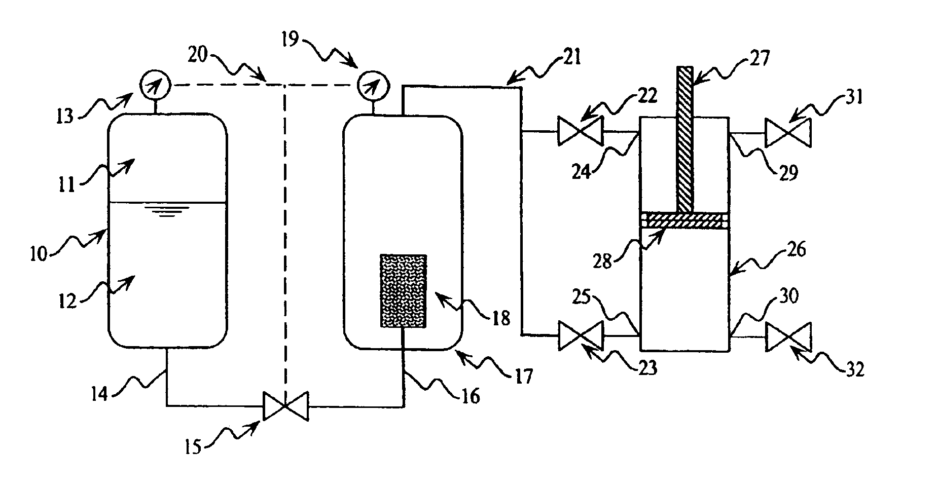
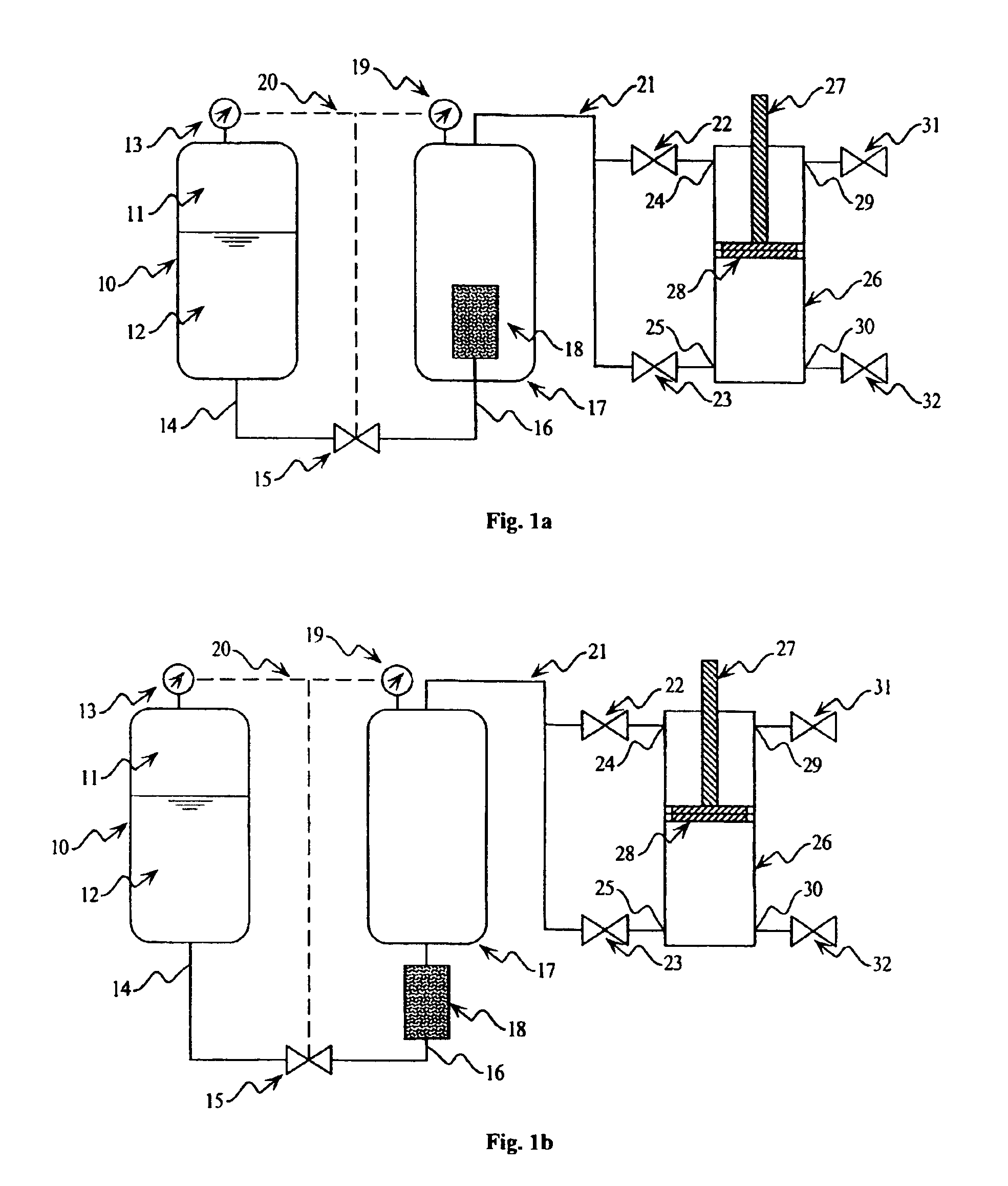
[0044]FIG. 1A illustrates a centralized monopropellant actuator embodiment. In this embodiment, the chemical energy of a monopropellant is released and stored in a central location and used to drive one or more pneumatic-type actuators. To this end, a blowdown fuel tank 10 is pre-pressurized with nitrogen or other inert gas 11 such that a monopropellant 12 is maintained at a sufficiently high pressure as measured by the pressure gage 13. The flow of monopropellant through a fuel line 14 is controlled by either a proportional or on / off liquid valve 15. Being driven by the higher pressure of the fuel tank 10, the monopropellant flows through line 14, through valve 15 (if it is open or partially open), and through line 16. Line 16 enters the pressure reservoir 17 where the monopropellant disassociates and expands into gaseous products within the catalyst pack 18. After disassociation, the gaseous products flow through the top of the screened surface of 18 into the pressure ...

second embodiment (

FIGS. 2A-2D)

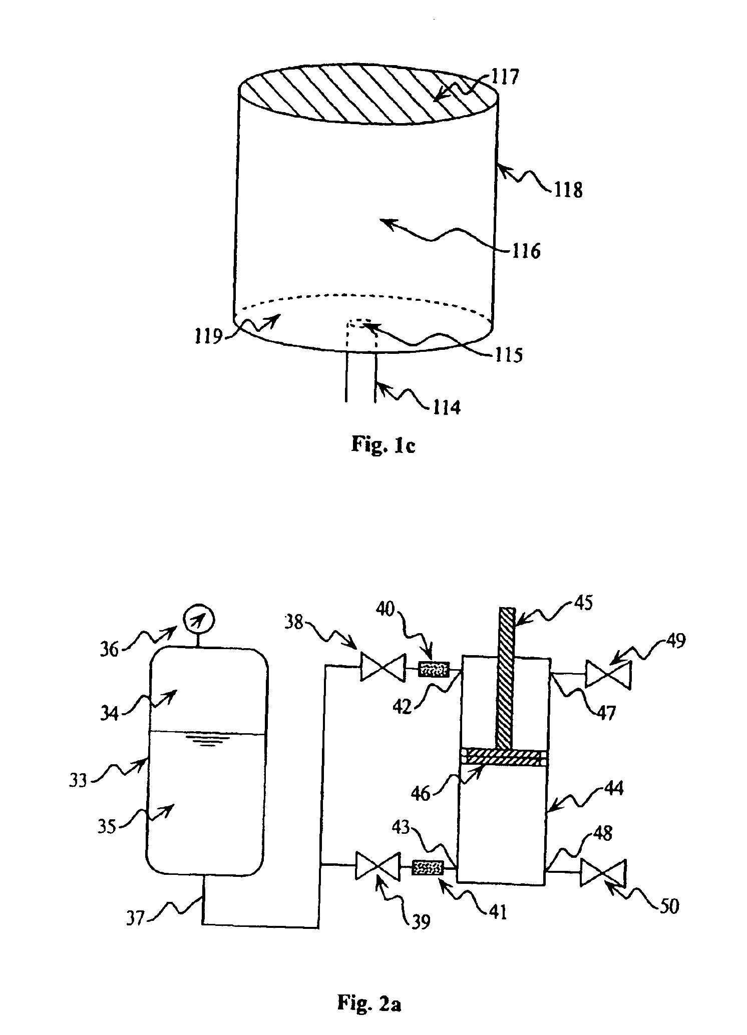
[0048]FIG. 2A illustrates a distributed monopropellant actuator embodiment. In this embodiment, the chemical energy of a monopropellant is distributed to one or more pneumatic-type actuators and released in a controlled manner inside the appropriate cylinder of the appropriate actuator. Shown in FIG. 2A is a blowdown fuel tank 33 pre-pressurized with an inert gas 34 and containing a monopropellant 35. This fuel tank 33 is instrumented with a pressure sensor 36 such that the pressure of the monopropellant liquid can be monitored. The liquid monopropellant is delivered via line or lines 37 to various pneumatic-type actuators (such as 44). Proportional valves 38 or 39 control the flow of monopropellant such that it flows through a catalyst pack 40 and / or 41. The catalyst packs contain catalytic agents such that the monopropellant may flow into, disassociate inside, and flow out of the pack without the catalytic agent being allowed to escape. The gaseous products of the mono...

third embodiment (fig.3)

Third Embodiment (FIG. 3)

[0051]FIG. 3 illustrates a distributed hypergolic bipropellant powered actuator embodiment. In this embodiment, a liquid (or gaseous) fuel and a liquid (or gaseous) oxidizer constituting a hypergolic bipropellant mixture are delivered to one or more pneumatic-type actuators. The chemical energy of the fuel is released upon contact with the oxidizer locally within each actuator. With regard to a liquid fuel and liquid oxidizer, FIG. 3 illustrates one possible configuration of this embodiment. A blowdown fuel tank 51 is pre-pressurized with an inert gas 52 such that the fuel 53 is under pressure and is monitored by pressure sensor 54. A similar blowdown tank 56 contains a pre-pressurized inert gas 57 such that the oxidizer 58 is under pressure and is monitored by pressure sensor 59. Fuel and oxidizer is transported to a pneumatic-type actuator via lines 55 and 60 respectively. Proportional control valves 61 and 62 control the flow of fuel while proportional co...


PUM

PropertyMeasurementUnit
depthaaaaaaaaaa
pressureaaaaaaaaaa
forcesaaaaaaaaaa

Abstract

Systems and methods involving monopropellant and hypergolic powered proportional actuators that may be used in applications such as robotics. A blowdown tank delivers fuel to a reaction site, produce gaseous products. Those gaseous products are transported to a pressure reservoir or directly to the actuator. The gaseous products are controllably introduced into the actuator to actuate a piston. The piston may be used to power a host of devices including robots.

Description

[0001]This application is a national phase application under 35 U.S.C. § 371 of International Application No. PCT / US02 / 30778 filed 26 Sep. 2002, which claims priority to U.S. Provisional Application No. 60 / 325,312 filed 27 Sep. 2001, the contents of which are incorporated herein by reference in their entirety.BACKGROUND OF THE INVENTION[0002]1. Field of the Invention[0003]The present invention relates generally to the fields of monopropellants, hypergolic bipropellants, robotic actuators, and robotic power sources. More particularly, it concerns the use of a monopropellant or hypergolic bipropellant to power a robotic actuator. Even more particularly, the liquid fuels are utilized to generate gaseous products, which are in turn used to proportionally control the force or motion of a gas actuator.[0004]2. Description of Related Art[0005]A major concern facing those who design and build untethered mobile robots involves finding a suitable source of power and actuation for those robots...

Claims


Application Information

Patent Timeline
Patent Type & Authority Patents(United States)
IPC IPC(8): B25J9/14B25J9/10C06D5/00C06D5/04C06B47/00C06B47/02F15B1/00F15B1/26F15B11/00F02B43/00F02B75/00F02G1/00F15B15/20F15B15/00F03C99/00C06C5/00F01B17/00
CPCB25J9/1095B25J9/144C06B47/02C06C5/00C06D5/00C06D5/04F01B17/00F02B43/00F02B75/00F02G1/00F15B1/265F15B11/006F15B2015/208F15B2211/21F15B2211/212F15B2211/30575F15B2211/40515F15B2211/41518F15B2211/428F15B2211/455Y02T10/32Y02T10/30
Inventor GOLDFARB, MICHAELWEHRMEYER, JOSEPHBARTH, ERICSTRAUSS, ALVIN
Owner VANDERBILT UNIV
Why Eureka
Try Eureka