
Exhaust nozzle segmented basesheet and production method thereof

a technology of exhaust nozzles and basesheets, which is applied in the direction of turbines, jet flaps, manufacturing tools, etc., can solve the problems of thermally induced distortion, premature failure of flaps, warping, cracking, etc., and achieves the effect of reducing the number of nozzles

Active Publication Date: 2005-08-30
GENERAL ELECTRIC CO
View PDF7 Cites 18 Cited by
  • Summary
  • Abstract
  • Description
  • Claims
  • Application Information

AI Technical Summary

Benefits of technology

"The patent describes a basesheet for use in a gas turbine engine exhaust nozzle. The basesheet is made up of multiple segments with stiffeners that have flanges that connect to the segment's panel body. The stiffeners have flanges that are resistance welded together to ensure strength and durability. The technical effect of this design is to provide a reliable and durable basesheet for the gas turbine engine exhaust nozzle that can withstand high temperatures and loads."

Problems solved by technology

Continued operation with the thermal gradient may induce thermal stresses into the basesheet which over time, may lead to warping, thermally induced distortion, cracking, or premature failure of the flaps.
However, because the center portion of the associated flap basesheets are still exposed to the hot combustion gases, thermal gradients between the basesheet edges and basesheet center portion may cause warping, cracking, or thermally induced distortion within the flap assembly.
However, aligning the basesheets while attaching the channel to the backside of the basesheets may be time consuming.
Furthermore, because the channel is attached across the basesheet and between the edges of the basesheet, continued thermal cycling may create local stress concentrations between the channel and the basesheet.

Method used


Image

  • Exhaust nozzle segmented basesheet and production method thereof
  • Exhaust nozzle segmented basesheet and production method thereof
  • Exhaust nozzle segmented basesheet and production method thereof

Examples


Embodiment Construction

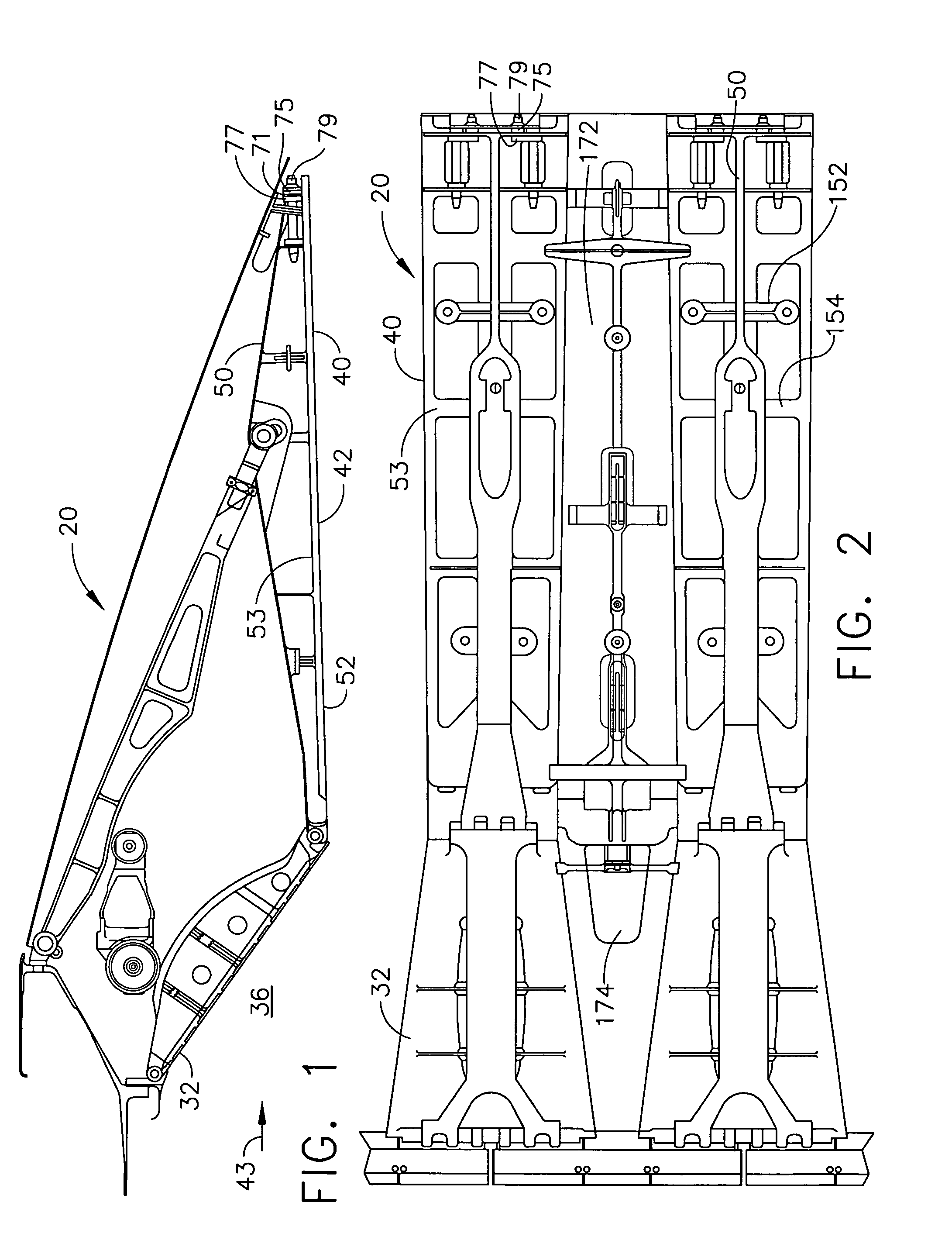
[0021]Illustrated in FIGS. 1 and 2 is a gas turbine engine variable geometry exhaust nozzle 20 including convergent flaps 32 and seals 174 and divergent flaps 40 and seals 172. Flowpath sides 42 of the divergent flaps 40 are exposed to hot exhaust gases 43 exiting the exhaust nozzle 20 and, thus, flowpath sides 42 define a portion of a flowpath 36 through the nozzle.

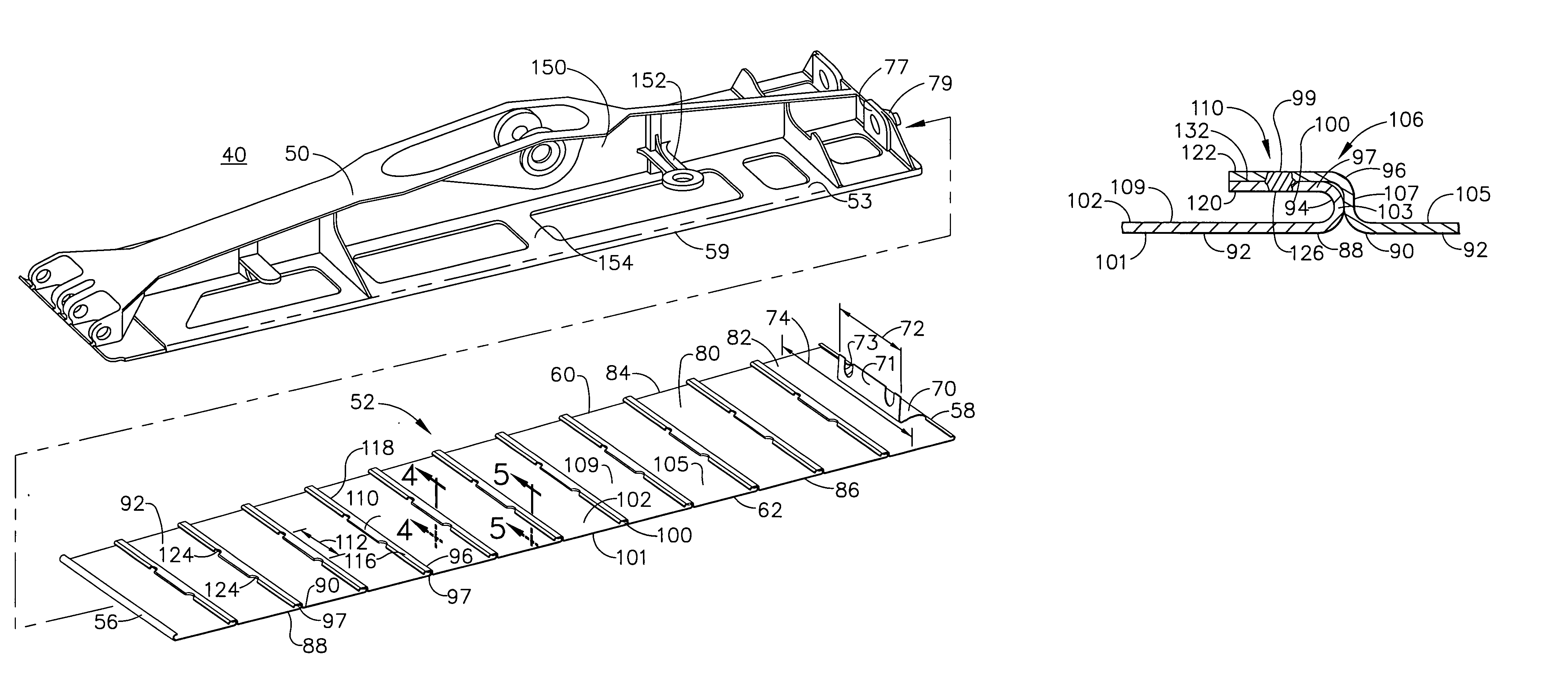
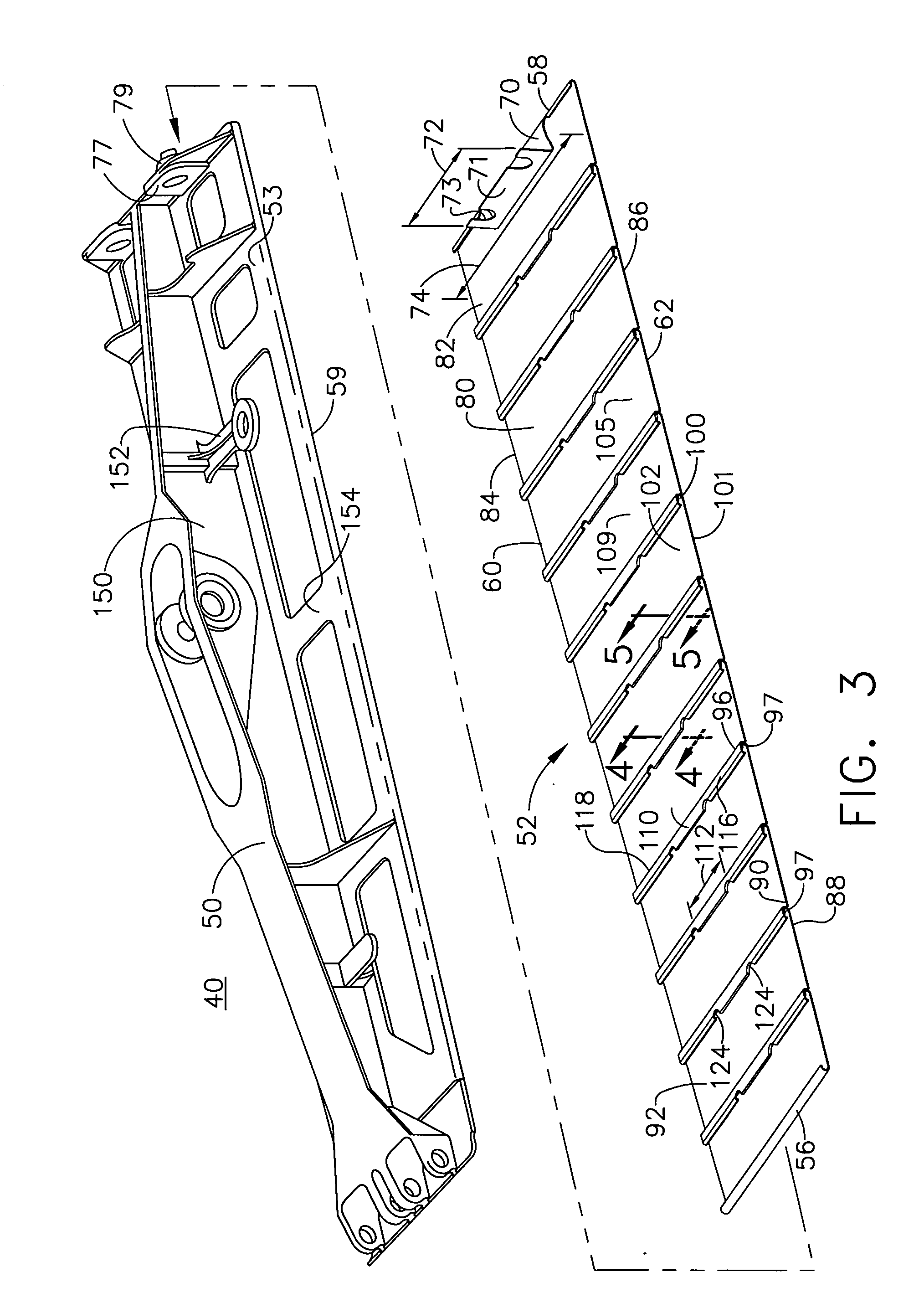
[0022]Illustrated in FIG. 3 is a partially exploded view of the divergent flap 40 which includes a longitudinally extending backbone 50 supporting a frame 53 for holding a removable basesheet 52. The basesheet 52 is constructed from a plurality of basesheet segments 80 connected together. The frame 53 is more particularly illustrated in cross-section in FIG. 6. The frame 53 supports a widthwise extending out-rigger 152 and includes longitudinally extending axial ribs 150. The cross-ribs 154 extend widthwise outwardly from the extending axial rib 150 of the frame 53. The basesheet 52 has right and left hand basesheet side...


PUM

PropertyMeasurementUnit
resistanceaaaaaaaaaa
exit areasaaaaaaaaaa
temperaturesaaaaaaaaaa

Abstract

A basesheet for use in an aircraft gas turbine engine exhaust nozzle includes a plurality of basesheet segments extending between longitudinally extending spaced apart basesheet leading and trailing edges, respectively, of the basesheet. Right and left hand basesheet side edges, respectively, extend longitudinally between the basesheet leading and trailing edges. Each basesheet segment has a panel body defined between a pair of segment side edges longitudinally extending between segment leading and trailing edges, respectively. Stiffeners having leading and trailing edge ribs at the segment leading and trailing edges of aft and forward ones of the basesheet segments, respectively, extend widthwise across the panel body between the segment side edges. The leading and trailing edge ribs are joined together only at intermediate sections of the stiffeners which are centered between left and right hand expansion sections, respectively, of the stiffener.

Description

BACKGROUND OF THE INVENTION[0001]1. Field of the Invention[0002]This invention relates generally to gas turbine engine nozzles and, more particularly, to methods and apparatus for sealing gas turbine engine nozzles with segmented flap basesheets.[0003]2. Description of Related Art[0004]Military aircraft gas turbine engines often include variable geometry exhaust nozzles. The variable geometry exhaust nozzle varies throat and exit areas of the exhaust nozzle using flaps and seals. Examples of such engines are the General Electric F110 and the F414. The flaps and seals define the flowpath and the seals as their name implies seal against adjacent flaps. Because the exhaust nozzles are subjected to high temperatures and thermal gradients as a result of hot combustion gases exiting the engine, the variable geometry nozzle must maintain a coherent flowpath while shielding nozzle structural components.[0005]Diverging flaps incorporating backbones to secure the basesheets have been used for...

Claims


Application Information

Patent Timeline
Patent Type & Authority Patents(United States)
IPC IPC(8): B23K11/11B64D33/04B64D33/00F02K1/12F02K1/00F02K1/80
CPCB23K11/115B64D33/04F02K1/805F02K1/12B23K2201/001Y10T29/49346F05D2230/20B23K2101/001
Inventor GOULD, KENNETH ARTHURBURNHAM, STEPHEN RUSSELL
Owner GENERAL ELECTRIC CO
Learn More