Reciprocating and rotary magnetic refrigeration apparatus

a magnetic refrigeration and reciprocating technology, applied in the field of magnetic refrigeration equipment, can solve the problems of not providing a complete and specific application for magnetic refrigeration equipment, and not being adequate for most magnetic refrigeration applications, and achieve the effect of increasing magnetic field intensity and enhancing magnetic field intensity

Inactive Publication Date: 2005-08-30
IND TECH RES INST
View PDF9 Cites 100 Cited by
  • Summary
  • Abstract
  • Description
  • Claims
  • Application Information

AI Technical Summary

Benefits of technology

[0008]The apparatus according to the invention has permanent magnets deployed on the stator and rotor. Two adjacent magnetic supply coils alternately receive current to generate magnetic resistance and magnetic torque similar to the way a dynamo attracts a rotor to rotate reciprocally. Through the permanent magnets located on the stator and rotor, the magnetic path forms by the magnetic supply coils surrounding the magnetocaloric material. Magnetization and demagnetization of the magnetocaloric material may help to increase magnetic field intensity.

Problems solved by technology

However, it does not provide a complete and specific application for the magnetic refrigeration apparatus.
This is not adequate for most magnetic refrigeration applications.

Method used


Image

  • Reciprocating and rotary magnetic refrigeration apparatus
  • Reciprocating and rotary magnetic refrigeration apparatus
  • Reciprocating and rotary magnetic refrigeration apparatus

Examples


Embodiment Construction

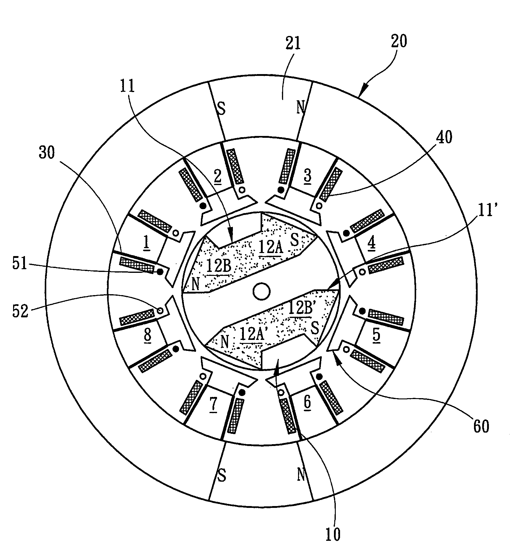
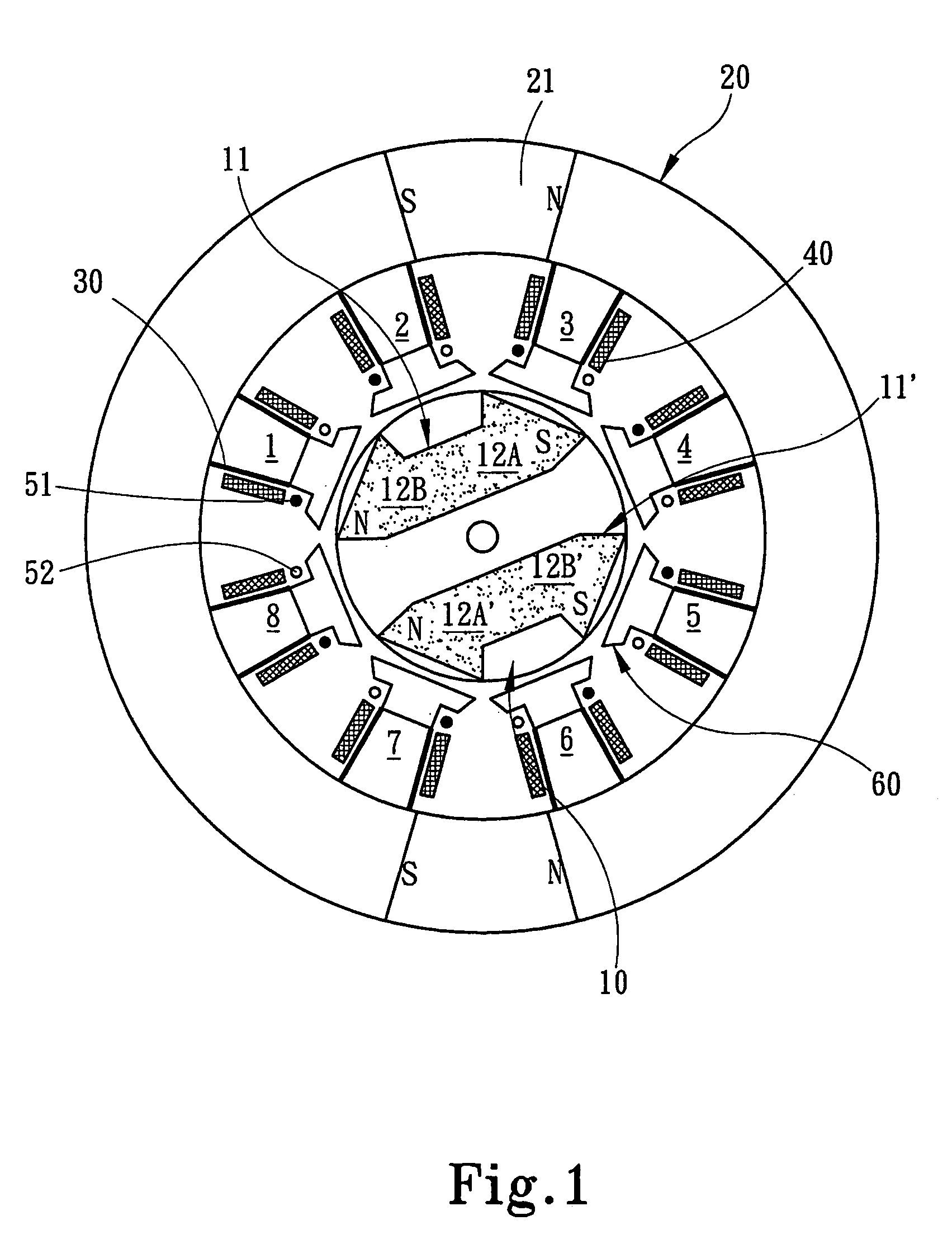
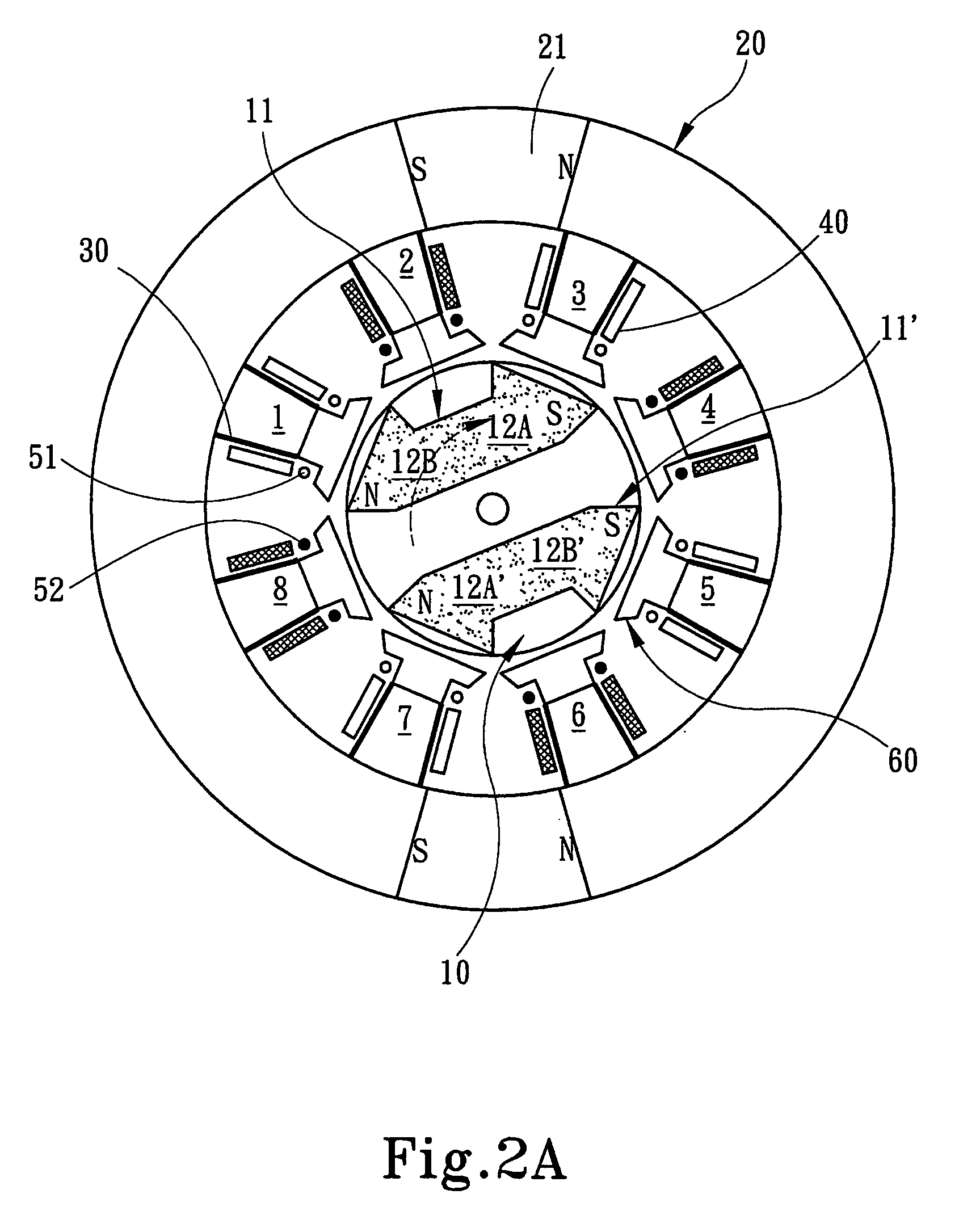
[0013]Please refer to FIG. 1; the reciprocating and rotary magnetic refrigeration apparatus according to the invention includes:[0014]a rotor 10 located in the center of the apparatus including a permanent magnet 11 which has two magnetic poles N and S, which rotate freely;[0015]a stator 20 which is an annular element surrounding the rotor 10. The stator 20 also has a permanent magnet 21, which has two magnetic poles N and S;[0016]Nose pole heads 1–8 are evenly spaced on the inner perimeter of the stator 20. Magnetocaloric materials 30 mount on the surface of each nose pole heads 1–8, respectively. Magnetic supply coils 40 surround the stator nose poles 1–8. Similar to the way a dynamo attracts a rotor to rotate reciprocally. Current alternately feeds into any two adjoining magnetic supply coils 40 to generate magnetic resistance and magnetic torque. The permanent magnet 11 of the rotor 10 and the electromagnetic field of the magnetic supply coils 40 form a magnetic path to magnetiz...


PUM


Abstract

A reciprocating and rotating magnetic refrigeration apparatus adopts a dynamo concept and the design of magnetic supply path and heat transfer unit to alternately magnetize and demagnetize a magnetocaloric material to generate thermo-magnetic effect for cooling. The apparatus includes magnetocaloric material located on the head of stator nose poles, magnetic supply coils surrounding the magnetocaloric material, permanent magnets located on a rotating stator, and a heat transfer unit in contact with the magnetocaloric material. Two adjacent magnetocaloric materials magnetize and demagnetize alternately to alter the temperature and entropy of the magnetocaloric material, and through the heat transfer unit, heat exchange occurs between the magnetocaloric materials and the atmosphere to achieve the cooling effect.

Description

FIELD OF THE INVENTION[0001]The present invention relates to a magnetic refrigeration apparatus and particularly to a reciprocating and rotary magnetic refrigeration apparatus. The invention uses reconfigured magnetocaloric material and a magnetization and demagnetization mechanism. A Reciprocating and rotary operation alternately magnetizes and demagnetizes the magnetocaloric material. The device is coupled with a design that includes a magnetic supply path and a heat transfer unit to generate a thermomagnetic effect.BACKGROUND OF THE INVENTION[0002]Warburg first discovered the thermo-magnetic effect in 1881. Warburg found that by placing selected materials in a magnetic field resulted in a temperature increase. Likewise, removing selected materials from the magnetic field causes a reduction in temperature. Thereafter a lot of effort has been devoted to exploring possible applications for the interaction of electromagnetic and thermal energy. Results of the thermo-magnetic effect v...

Claims


Application Information

Patent Timeline
Patent Type & Authority Patents(United States)
IPC IPC(8): F25B21/00
CPCF25B21/00H02K5/12H02K9/00H02K33/16F25B2321/0022Y02B30/66Y02B30/00
Inventor FANG, CHIH-HSINGHUANG, WEN-NANCHEN, CHIH-HSINCHEN, WAN-PEIHWU, KUO-ING
Owner IND TECH RES INST
Why Eureka
Try Eureka