Test method for assessing thermal mechanical fatigue performance of a test material

a test material and thermal mechanical fatigue technology, applied in the field of aircraft gas turbines, can solve problems such as complex test cycle, and achieve the effect of good indicator of material susceptibility

Inactive Publication Date: 2005-08-30
GENERAL ELECTRIC CO
View PDF8 Cites 14 Cited by
  • Summary
  • Abstract
  • Description
  • Claims
  • Application Information

AI Technical Summary

Benefits of technology

[0013]The rib should be maintained in compression while the rib is heated toward the higher rib temperature during the heating part of the cycle. However, the rib may go into tension if the rib compressively yields or creeps. Likewise, the rib goes into tension during cooling. This stress state is achieved by having the average rib temperature higher than the average base temperature during heating and lower during cooling, and by having the base sufficiently stiff t...

Problems solved by technology

The test cycle may be complex, with several st...

Method used


Image

  • Test method for assessing thermal mechanical fatigue performance of a test material
  • Test method for assessing thermal mechanical fatigue performance of a test material
  • Test method for assessing thermal mechanical fatigue performance of a test material

Examples


Embodiment Construction

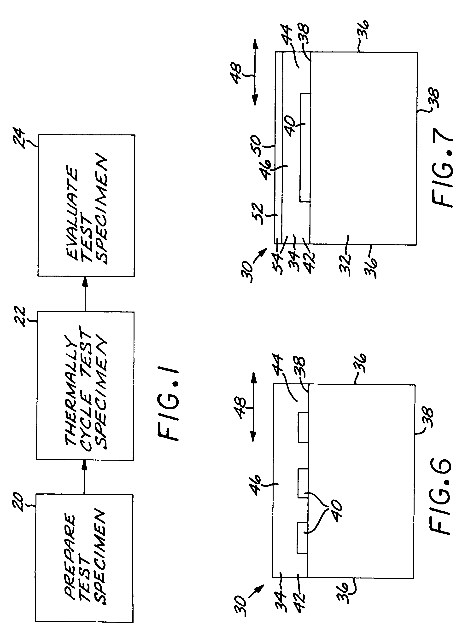
[0023]FIG. 1 depicts an embodiment of a test method for testing the thermal mechanical fatigue performance of a test material. The test method first includes preparing a test specimen 30 of the test material, step 20. The test material is preferably a nickel-base superalloy. As used herein, “nickel-base” means that the composition has more nickel present than any other element. The nickel-base superalloys are typically of a composition that is strengthened by the precipitation of gamma-prime phase or a related phase. The test material may instead be other metallic materials, a ceramic, or a combination of materials.

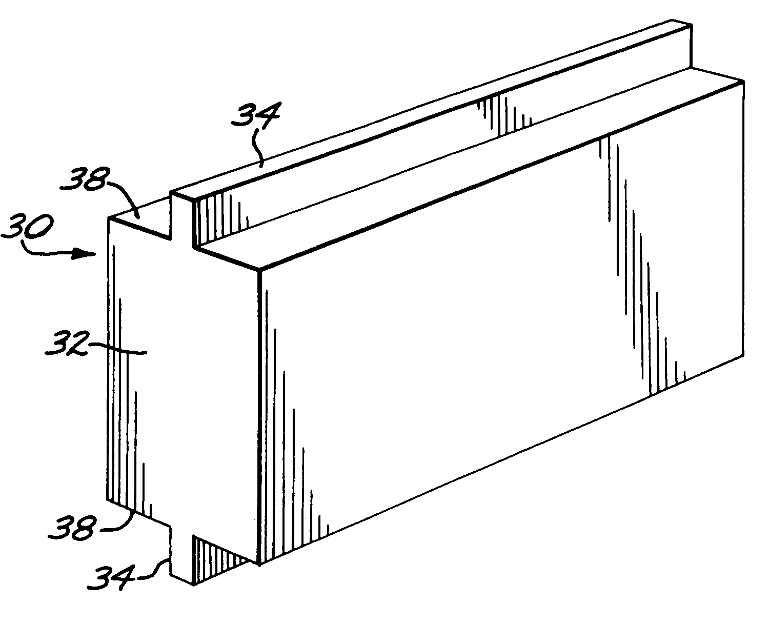
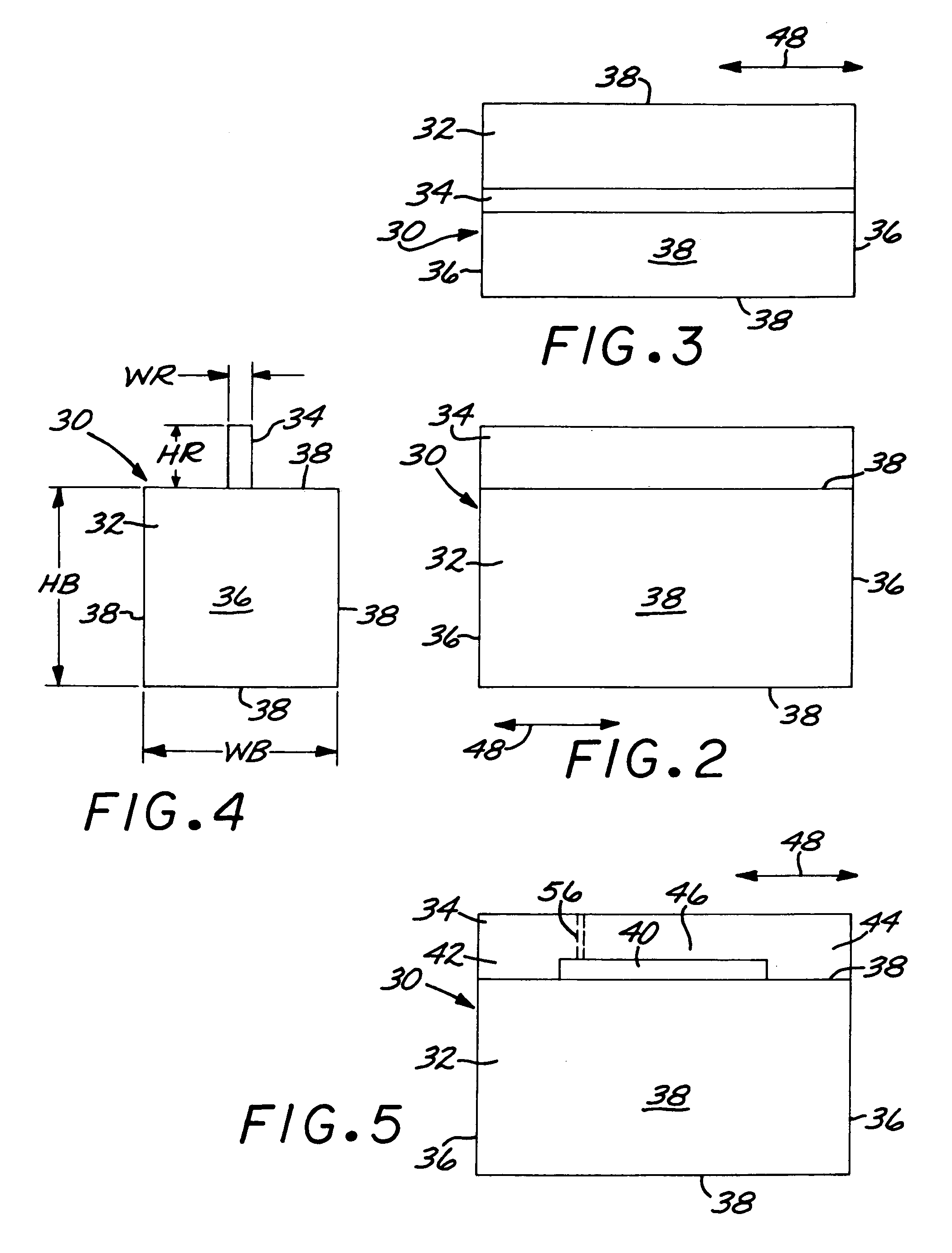
[0024]FIGS. 2–4 illustrate an embodiment of the test specimen 30. The test specimen 30 comprises a base 32, and at least one rib 34 extending outwardly from the base 32. As illustrated, the base 32 is a rectangular prism with two parallel ends 36 and four lateral faces 38. The rib 34 extends outwardly from one of the lateral faces 38.

[0025]The base 32 must have a much lar...


PUM


Abstract

A test method for testing the thermal mechanical fatigue performance of a test material includes preparing a test specimen of the test material, wherein the test specimen has a base, and a rib extending outwardly from the base. The test specimen is thermally cycled through at least one test cycle. In each test cycle the rib is heated to a higher rib temperature and thereafter cooled to a lower rib temperature. The test specimen is evaluated for thermal mechanical fatigue damage.

Description

[0001]This invention relates to the testing of materials and, more particularly, to evaluating the thermal mechanical fatigue performance of materials used in aircraft gas turbine engines.BACKGROUND OF THE INVENTION[0002]In an aircraft gas turbine (jet) engine, air is drawn into the front of the engine, compressed by a shaft-mounted compressor, and mixed with fuel. The mixture is combusted, and the resulting hot combustion gases are passed through a turbine mounted on the same shaft. The flow of gas turns the turbine by contacting an airfoil portion of the turbine blade, which turns the shaft and provides power to the compressor. The hot exhaust gases flow from the back of the engine, driving it and the aircraft forward. There may additionally be a bypass fan that forces air around the center core of the engine, driven by a shaft extending from the turbine section.[0003]In service, the components of the turbine section of the engine are repeatedly thermally cycled between lower and ...

Claims


Application Information

Patent Timeline
IPC IPC(8): G01N3/32G01N3/02G01N3/00
CPCG01N3/32G01N2203/0005G01N2203/0057G01N2203/0073G01N2203/0224G01N2203/0262
Inventor GORMAN, MARK DANIELSRIVATSA, SHESH KRISHNAWRIGHT, III, PHILEMON KENNARDGOVERN, CHRISTINE
Owner GENERAL ELECTRIC CO
Why Eureka
Try Eureka