Mitigating risk by using fracture mapping to alter formation fracturing process

a technology of fracture mapping and formation fracturing, applied in the direction of survey, fluid removal, borehole/well accessories, etc., can solve the problem of undesired fracture and achieve the effect of reducing the risk of hydrocarbon productivity

Inactive Publication Date: 2005-08-30
HALLIBURTON ENERGY SERVICES INC
View PDF34 Cites 44 Cited by
  • Summary
  • Abstract
  • Description
  • Claims
  • Application Information

AI Technical Summary

Benefits of technology

[0007]The present invention meets the aforementioned need by providing a method for fracturing a formation in a manner to mitigate risk to hydrocarbon productivity arising from the fracturing. This method comprises: pumping fracturing fluid, during at least part of a fracturing job time period, into a well to initiate or extend a fracture in a formation with which the well communicates; generating signals, within the fracturing job time period, in response to at least one dimension of the fracture; and further pumping fracturing fluid, within the fracturing job time period, into the well in response to the generated signals, including controlling in response to the generated signals at least one of a pump rate of the further pumping and a viscosity of the further pumped fracturing fluid.

Problems solved by technology

Unfortunately, this does not always happen because the fracturing process can damage rather than help the formation.
As another example, fracturing can occur in an undesired manner, such as with a fracture extending vertically into an adjacent water-filled zone.

Method used


Image

  • Mitigating risk by using fracture mapping to alter formation fracturing process
  • Mitigating risk by using fracture mapping to alter formation fracturing process
  • Mitigating risk by using fracture mapping to alter formation fracturing process

Examples


Embodiment Construction

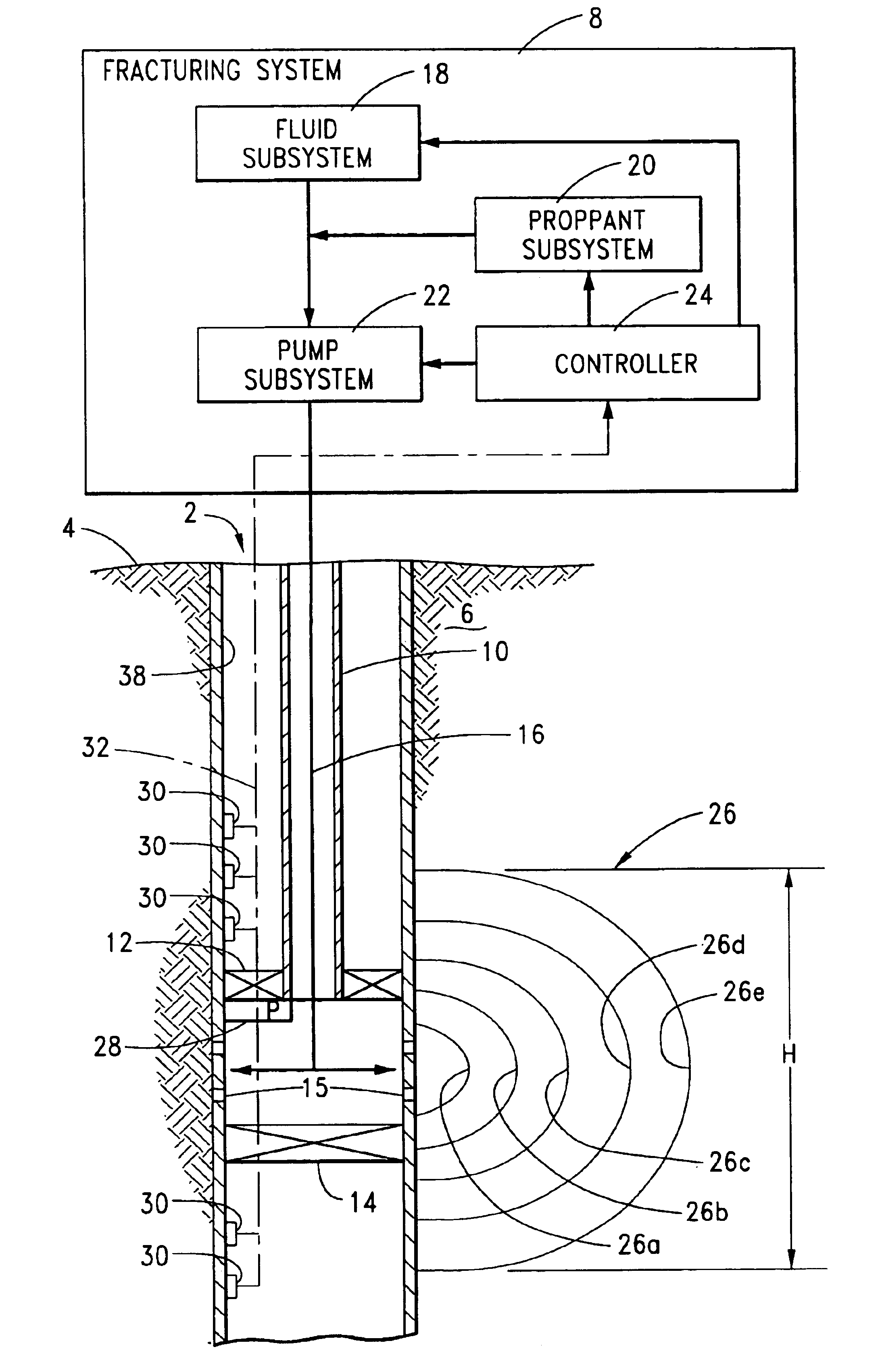
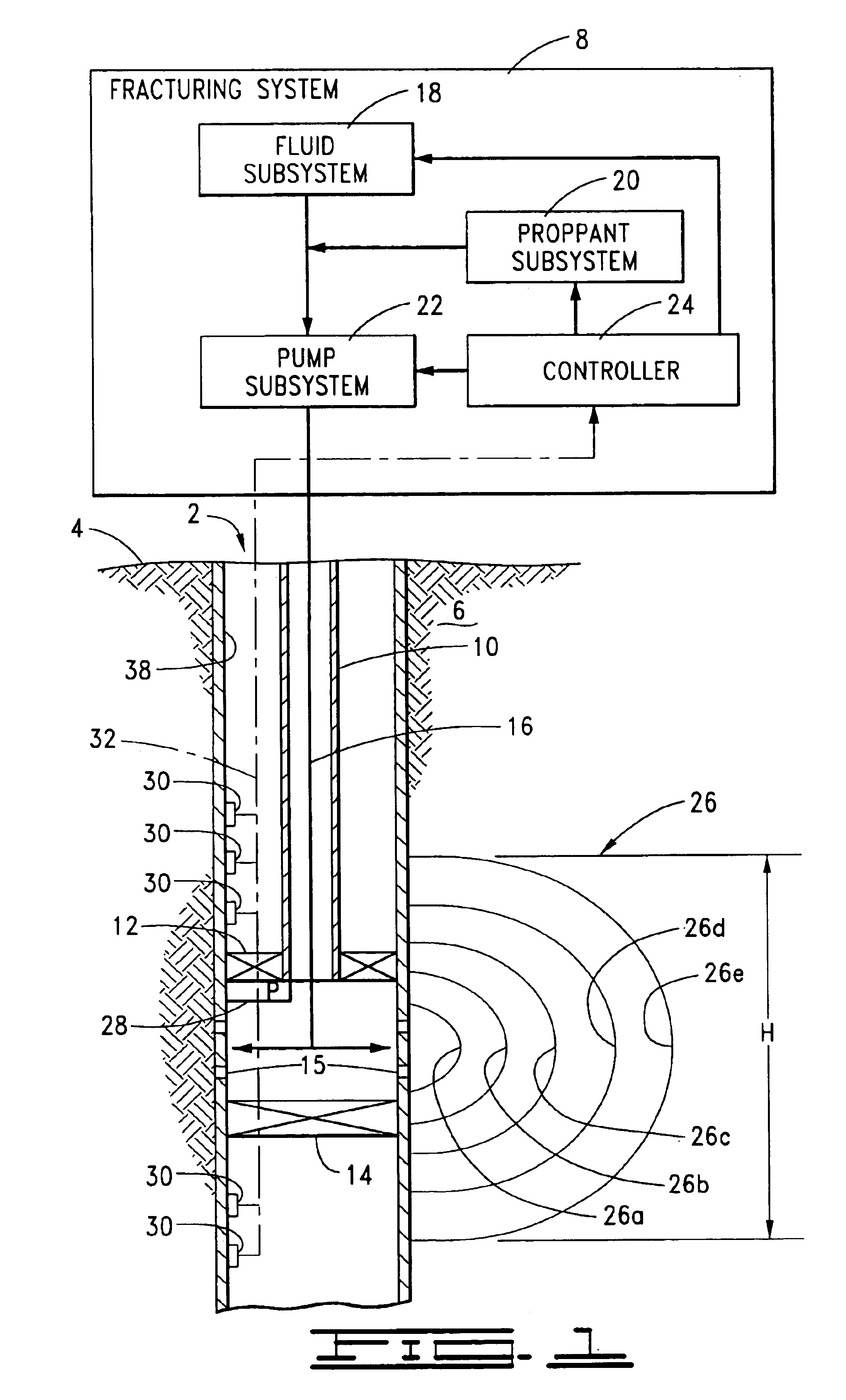
[0016]Referring to FIG. 1, a cased or uncased well 2 formed in the earth 4 (whether terrestrial or subsea) in a suitable manner known in the art communicates with a subterranean formation 6. Specifically in FIG. 1, the well 2 intersects the formation 6 such that at least part of the well bore is defined by part of the formation 6. A fracturing fluid from a fracturing system 8 can be applied against such part of the formation 6 to fracture it. In one typical manner of doing so, a fluid-conductive pipe or tubing string 10 is suitably disposed in the well 2; and pack-off assembly 12 and bottom hole packer 14, or other suitable means, are disposed to select and isolate the particular surface of the formation 6 against which the fracturing fluid is to be applied through one or more openings in the pipe or tubing string 10 or casing or cement if such otherwise impede flow into the selected portion of the formation 6 (for example, through perforations 15 formed by a perforating process as ...


PUM


Abstract

A formation fracturing method with which to mitigate risk to hydrocarbon productivity includes pumping fracturing fluid, during at least part of a fracturing job time period, into a well to fracture a formation; generating signals, within the fracturing job time period, in response to at least one dimension of the fracture; and further pumping fracturing fluid, within the fracturing job time period, into the well in response to the generated signals. Further pumping includes controlling at least one of a pump rate of the further pumping and a viscosity (either fluid viscosity or particulate concentration) of the further pumped fracturing fluid. Control can include comparing a measured magnitude of at least one dimension of the fracture represented by the generated signals with a predetermined modeled magnitude of the same dimension. Tiltmeters can be used to sense fracture height and width, for example.

Description

BACKGROUND OF THE INVENTION[0001]This invention relates generally to methods for fracturing a formation communicating with a well, such as a hydrocarbon-bearing formation intersected by an oil or gas production well.[0002]There are various uses for fractures created in subterranean formations. In the oil and gas industry, for example, fractures may be formed in a hydrocarbon-bearing formation to facilitate recovery of oil or gas through a well communicating with the formation.[0003]Fractures can be formed by pumping a fracturing fluid into a well and against a selected surface of a formation intersected by the well. Pumping occurs such that a sufficient hydraulic pressure is applied against the formation to break or separate the earthen material to initiate a fracture in the formation.[0004]A fracture typically has a narrow opening that extends laterally from the well. To prevent such opening from closing too much when the fracturing fluid pressure is relieved, the fracturing fluid ...

Claims


Application Information

Patent Timeline
Patent Type & Authority Patents(United States)
IPC IPC(8): E21B49/00E21B43/25E21B43/26E21B47/02
CPCE21B43/26E21B47/02E21B49/006
Inventor LEHMAN, LYLE V.WRIGHT, CHRISTOPHER A.
Owner HALLIBURTON ENERGY SERVICES INC
Why Eureka
Try Eureka