Method and apparatus for expanding a welded connection

a threaded connection and expansion method technology, applied in the direction of borehole/well accessories, manufacturing tools, other domestic objects, etc., can solve the problems of increasing the diameter of the well, reducing the efficiency of the threaded connection, so as to achieve high reliability

Inactive Publication Date: 2005-08-30
WEATHERFORD TECH HLDG LLC
View PDF8 Cites 57 Cited by
  • Summary
  • Abstract
  • Description
  • Claims
  • Application Information

AI Technical Summary

Benefits of technology

[0013]The present invention generally relates to methods of connecting two expandable tubulars. In one aspect, the method includes flash welding the ends of the tubulars together. The flash welding process provides a highly reliable joint for expansion.
[0016]In another aspect, the present invention provides a method of completing a well. The method involves flash welding a first tubular to a second tubular. The method includes disposing a housing around an end of the first tubular and an end of the second tubular. Thereafter, a non-flammable gas may be provided within the housing to facilitate the welding process and / or prevent ingress of flammable mixtures of hydrocarbons. After the tubulars have been joined, the tubulars may be expanded downhole.

Problems solved by technology

However, one drawback of this process is that as the wellbore is extended, the inner diameter of the well progressively decreases.
Additionally, running expandable liners instead of long casing strings will result in valuable time savings.
A problem arises when the threaded connection is expanded.
However, the specifications of the threads do not take into account the expansion of the threaded connection.
For example, the tight metal-to-metal seal created between the female thread and the male thread becomes slack, thereby jeopardizing the seal at the threaded connection.

Method used


Image

  • Method and apparatus for expanding a welded connection
  • Method and apparatus for expanding a welded connection
  • Method and apparatus for expanding a welded connection

Examples


example

[0035]In one example, two expandable tubulars having about 2″ outer diameters and about 0.156″ wall thickness are joined in accordance with the aspects of the present invention. The initial spacing gap between the tubulars was 0.25″. The starting flash was set when the relative position between the two clamps was about 3.5″. The upset was initiated at a relative clamp position of about 2″ with an upset pressure of 600 psi. During the welding process, the voltage was set at about 12 VAC and the total cycle time including positioning was about 30 seconds. The final relative clamp position was between about 0.8″ to about 1.2″.

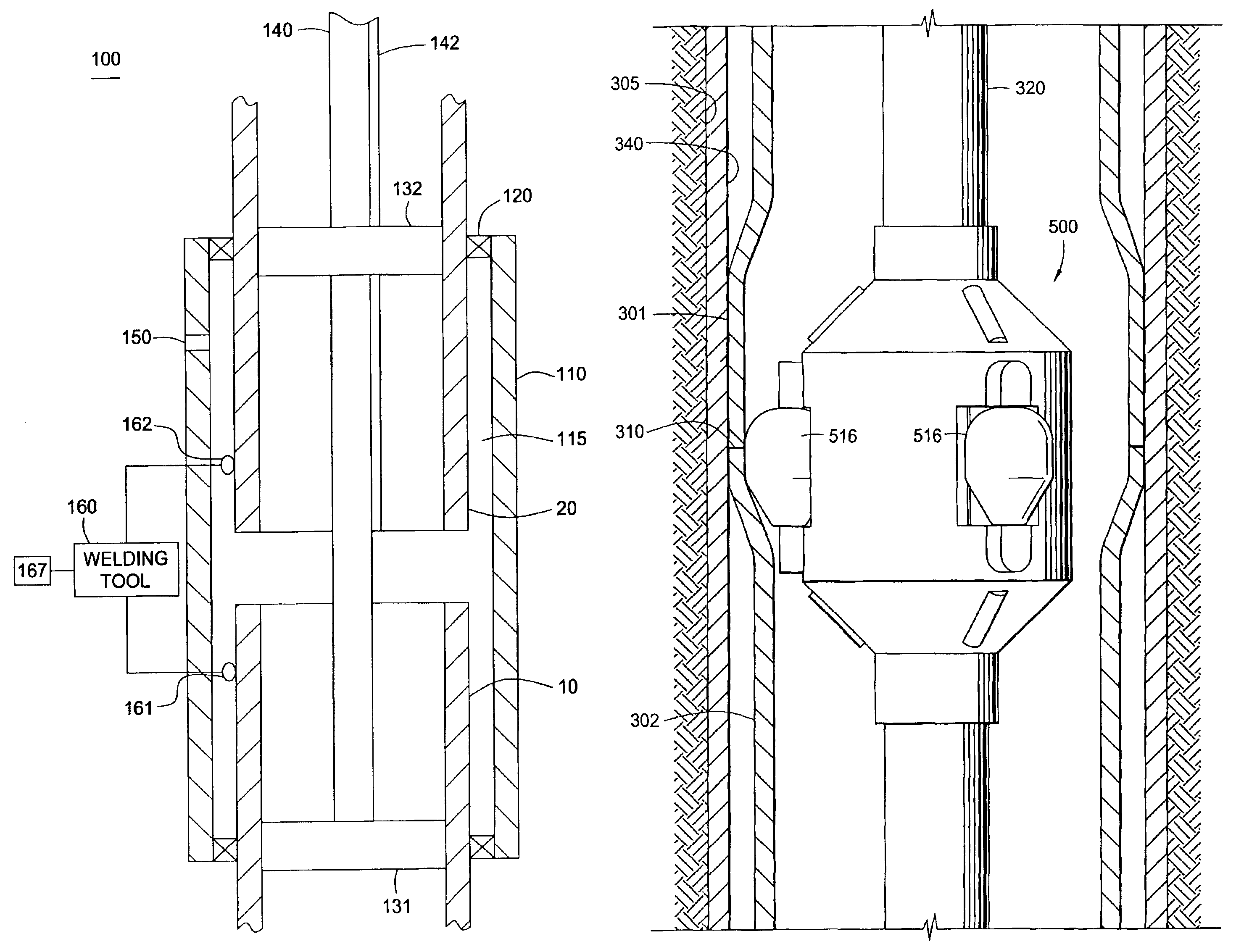
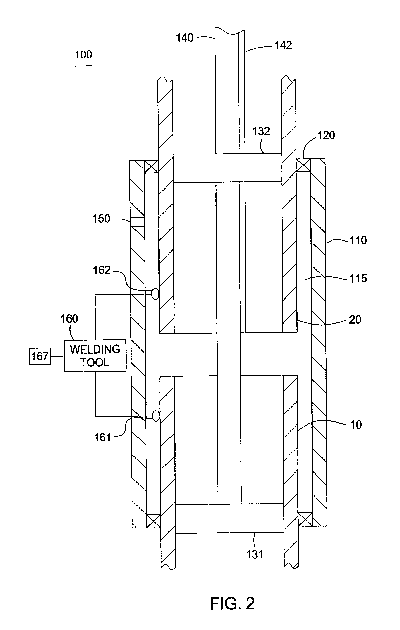
[0036]The flash welding process may optionally include an additional preheating action. In one embodiment, the ends of the tubulars 10, 20 may be caused to oscillate against each other. Initially, the ends are brought together to allow heat to be generated from the resistance of the tubulars 10, 20.

[0037]When the ends begin to cool and solidify, the preheating act...


PUM

PropertyMeasurementUnit
pressureaaaaaaaaaa
thicknessaaaaaaaaaa
lengthaaaaaaaaaa

Abstract

The present invention generally relates to methods of connecting two expandable tubulars. In one aspect, the method includes flash welding the ends of the expandable tubulars together. Thereafter, the connected tubulars are lowered into the wellbore for expansion. The flash welding process provides a highly reliable joint for expansion. In another aspect, the present invention provides a method for expanding a non-uniform tubular. In one embodiment, the non-uniform tubular is formed by connecting two misaligned tubulars.

Description

CROSS-REFERENCE TO RELATED APPLICATIONS[0001]This application is a continuation-in-part of co-pending U.S. patent application Ser. No. 10 / 356,360, entitled “Flash Welding Process For Field Joining of Tubulars For Expandable Application”, filed on Jan. 31, 2003, which patent application is herein incorporated by reference.BACKGROUND OF THE INVENTION[0002]1. Field of the Invention[0003]The present invention relates to wellbore completion. More particularly, the invention relates to apparatus and methods of connecting two tubulars. More particularly still, the invention relates to apparatus and methods of connecting two expandable tubulars at the well site.[0004]2. Description of the Related Art[0005]In the drilling of oil and gas wells, a wellbore is formed using a drill bit that moves downwardly at a lower end of a drill string. After drilling a predetermined depth, the drill string and bit are removed, and the wellbore is typically lined with a string of steel pipe called casing. Th...

Claims


Application Information

Patent Timeline
Patent Type & Authority Patents(United States)
IPC IPC(8): B23K11/04E21B17/08E21B17/02E21B43/10
CPCB23K11/04E21B17/08E21B43/106B23K2201/06B23K2101/06
Inventor HARRALL, SIMON J.METCALFE, PAUL D.BADRAK, ROBERT P.
Owner WEATHERFORD TECH HLDG LLC
Why Eureka
Try Eureka