Hybrid vehicle driving device

a hybrid vehicle and driving device technology, applied in mechanical energy handling, transportation and packaging, electric propulsion mounting, etc., can solve the problem of difficult transmission of heat output from the fluid transmitting device, and achieve the effect of preventing the rotor from shifting and reducing the axial length of the whole drive apparatus

Inactive Publication Date: 2005-08-30
AISIN AW CO LTD
View PDF15 Cites 54 Cited by
  • Summary
  • Abstract
  • Description
  • Claims
  • Application Information

AI Technical Summary

Benefits of technology

[0020]According to the present invention, the engine output shaft and the input member of the fluid transmitting apparatus are connected so as to freely move axially relative to each other. Accordingly, the rotor side is not affected by deformation of the fluid transmitting apparatus due to the centrifugal hydraulic pressure or the like.
[0021]According to another preferred embodiment of the present invention, the rotor and the input member of the fluid transmitting apparatus are integrally fixed so as to be rotatably supported by the case and are connected to the output shaft of the engine in a manner allowing free axial movement. Accordingly, it is possible to prevent the rotor from shifting relative to the stator.
[0022]According to yet another embodiment of the present invention, the rotor and the output shaft of the engine are integrally fixed so as to be rotatably supported by the case and are connected to the input member of the fluid transmitting apparatus in a manner allowing free axial movement in an axial direction relative to each other. Accordingly, in this embodiment also, it is possible to prevent the rotor from shifting relative to the stator.
[0023]In still another preferred embodiment of the present invention, the fluid transmitting apparatus has a front cover covering a turbine runner and serving as the input member connected to a pump impeller, the front cover has an axially extending portion and the rotor is arranged radially outward of the axially extending portion with the predetermined gap therebetween. Accordingly, the axial length of the whole of the drive apparatus can be reduced.
[0024]In the present invention, the predetermined gap is preferably within a range between 0.8 and 3.5 mm. Accordingly, it is possible to prevent dust such as iron powder from accumulating in a position close to the rotor, within the fluid transmitting apparatus, due to the magnetic flux output from the magnet of the rotor.
[0025]In another preferred embodiment of the present invention, the fluid transmission apparatus includes a multi-disc lockup clutch for connecting the input member to the turbine, and the lockup clutch is arranged radially inward of the axially extending middle portion of the front cover. Accordingly, given the aforementioned predetermined gap, it is possible to prevent dust such as iron powder from accumulating in the lockup clutch due to the magnetic flux output from the magnet of the rotor.

Problems solved by technology

Further, the heat output from the fluid transmitting device is not easily transmitted and the magnet of the rotor is not degaussed.

Method used


Image

  • Hybrid vehicle driving device
  • Hybrid vehicle driving device
  • Hybrid vehicle driving device

Examples


Embodiment Construction

[0036]Preferred embodiments of the present invention will now be described with reference to the accompanying drawings.

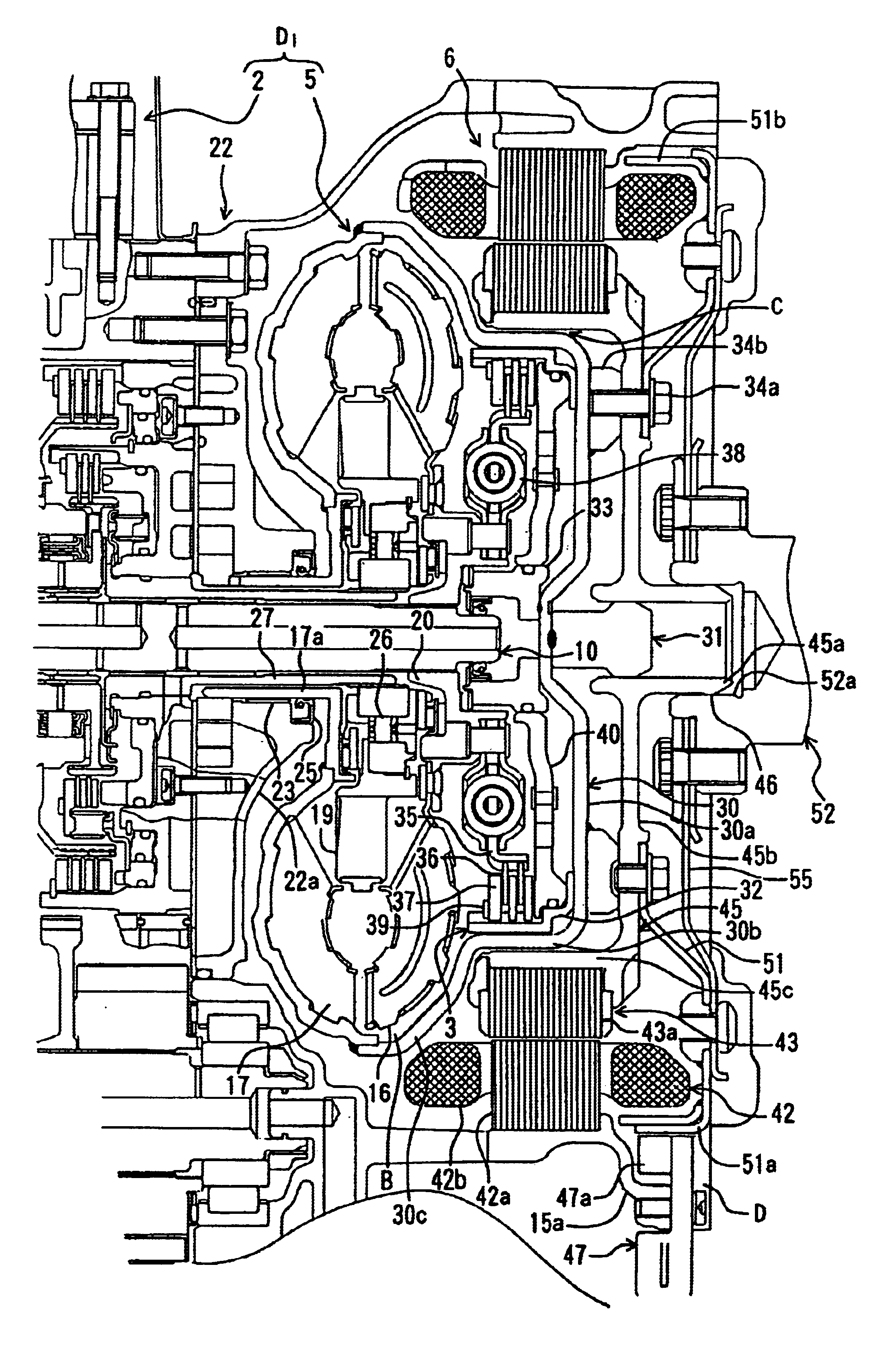
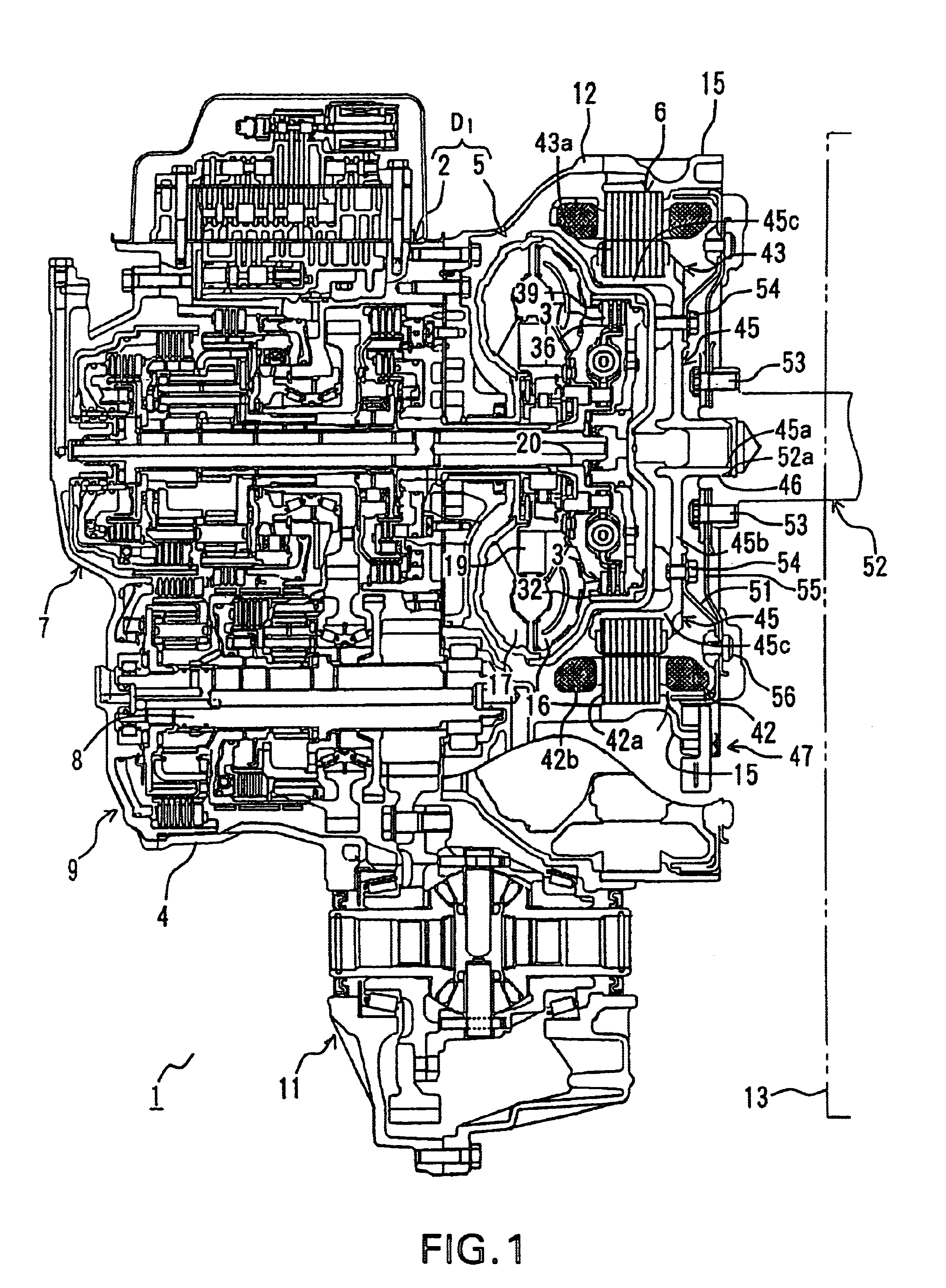
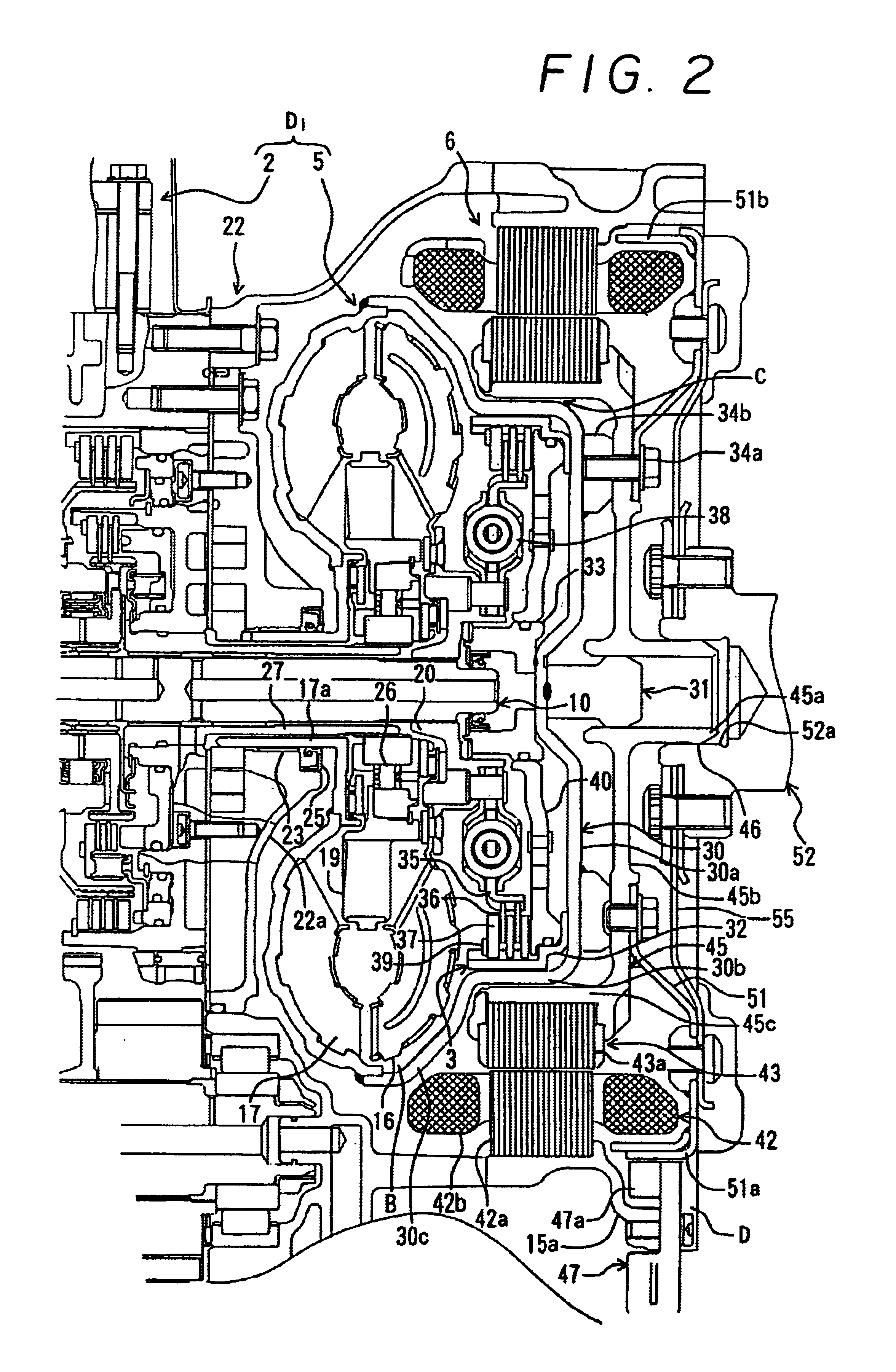
[0037]FIGS. 1 and 2 show a first preferred embodiment wherein a drive apparatus 1 for a hybrid vehicle includes an internal combustion engine 13 such as a gasoline engine or the like, a motor / generator (a motor) 6 in the form of a brushless DC motor or the like housed in a motor housing 15, and a conventional automatic transmission D1 to which a driving force output from the engine 13 and the motor / generator 6 are transmitted, with the motor / generator 6 mounted in a torque converter portion of the conventional automatic transmission D1. Thus, the drive apparatus 1 for a hybrid vehicle according to the invention is structured such that the motor / generator 6 and the automatic transmission D1 are arranged in sequence from one end of the engine.

[0038]A crankshaft (an output shaft) 52 extends from the internal combustion engine 13 to the motor / generator 6, and a flexible...


PUM


Abstract

A motor/generator is arranged radially outward of a middle portion of a front cover of a torque converter so that at least a part of the motor/generator axially overlaps the torque converter, with a predetermined gap (C) between the front cover and the rotor of the motor/generator. The rotor of the motor/generator is supported by either the torque converter or an engine crankshaft or by any two of the torque converter, a motor housing and the crankshaft. The rotor is not affected by the torque converter and the efficiency of the motor is not reduced.

Description

CROSS-REFERENCE TO RELATED APPLICATIONS[0001]This application is a National Phase Application (35 USC 371) of PCT / JP00 / 06766 and claims priority of Japanese Application No. 11-282177 filed Oct. 1, 1999, Japanese Application No. 2000-17885 filed Jun. 15, 2000 and Japanese Application No. 2000-292978 filed Sep. 26, 2000. This application is also related to U.S. Pat. No. 6,478,101 which also claims priority of Japanese Application 11-282177 filed Oct. 1, 1999 and Japanese Application No. 2000-179885 filed Jun. 15, 2000.TECHNICAL FIELD[0002]The present invention relates to a drive apparatus in a hybrid vehicle of a parallel type in which an engine and a motor are connected for use as power sources, and more particularly to a drive apparatus for a hybrid vehicle in which a motor is additionally provided in a casing housing a transmission mechanism.BACKGROUND ART[0003]Conventionally, a parallel type hybrid vehicle has both an engine and a motor / generator transmit driving forces to the aut...

Claims


Application Information

Patent Timeline
Patent Type & Authority Patents(United States)
IPC IPC(8): B60K6/04B60K6/00H02K7/18H02K7/00B60K6/26B60K6/383B60K6/40B60K6/485B60K6/547
CPCB60K6/26B60K6/383B60K6/40B60K6/485B60K6/547H02K7/006H02K7/1815Y02T10/6226Y02T10/62
Inventor TSUZUKI, SHIGEOINUZUKA, TAKESHIWAKUTA, SATORUKIDO, TAKAHIROTANIGUCHI, TAKAOTSUKAMOTO, KAZUMASAOMOTE, KENJI
Owner AISIN AW CO LTD
Why Eureka
Try Eureka