Magnet type clutch device or magnet type fan clutch device

a clutch device and magnet technology, applied in the direction of clutches, non-mechanical actuated clutches, fluid engines, etc., can solve the problem that the rotation speed of the fan cannot be arbitrarily changed, and achieve the effect of reducing noise, cost, and fuel cos

Inactive Publication Date: 2005-08-30
USUI KOKUSAI SANGYO KAISHA LTD
View PDF6 Cites 7 Cited by
  • Summary
  • Abstract
  • Description
  • Claims
  • Application Information

AI Technical Summary

Benefits of technology

[0011]In the magnet type clutch device or the magnet type fan clutch device in the present invention, the rotation speed of the output shaft such as a fan, etc. can be arbitrarily changed only by switching and controlling

Problems solved by technology

However, in the conventional magnet type fan clutch device, the magnet coupling is constructed by the permanent magnet rotating body and the permanent magnet mounted to this rotating body, and no directions of magnet fluxes o

Method used


Image

  • Magnet type clutch device or magnet type fan clutch device
  • Magnet type clutch device or magnet type fan clutch device
  • Magnet type clutch device or magnet type fan clutch device

Examples


Embodiment Construction

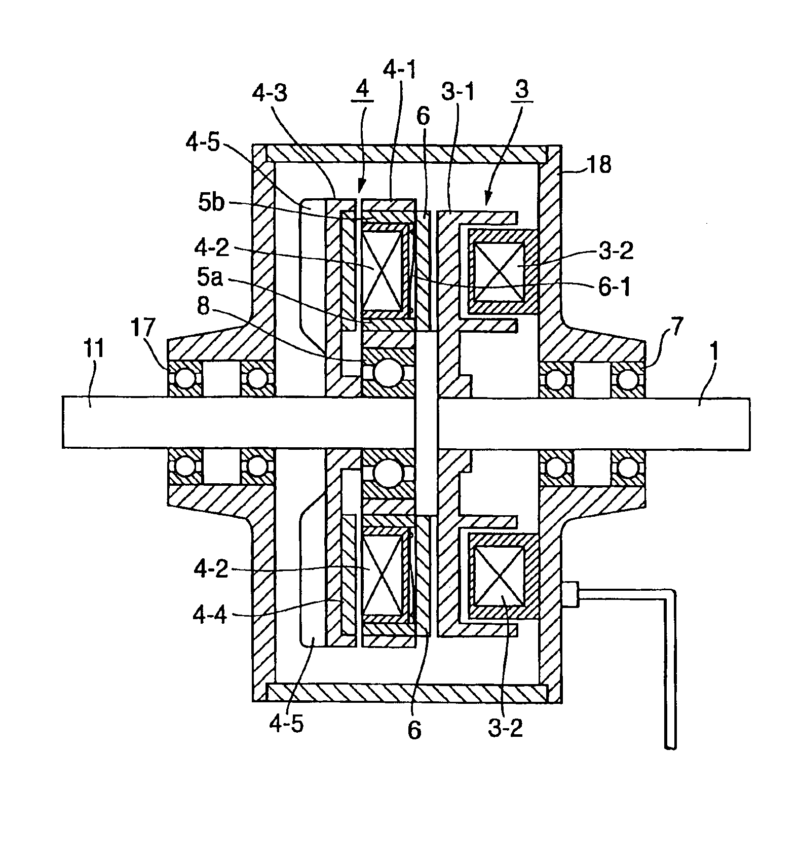
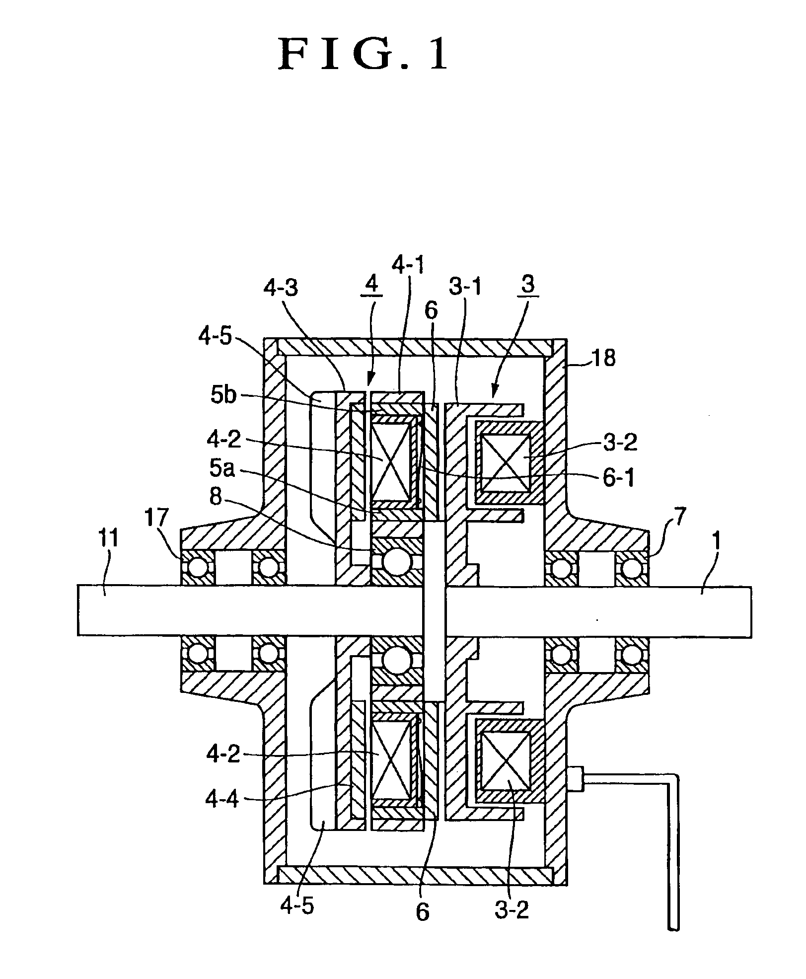
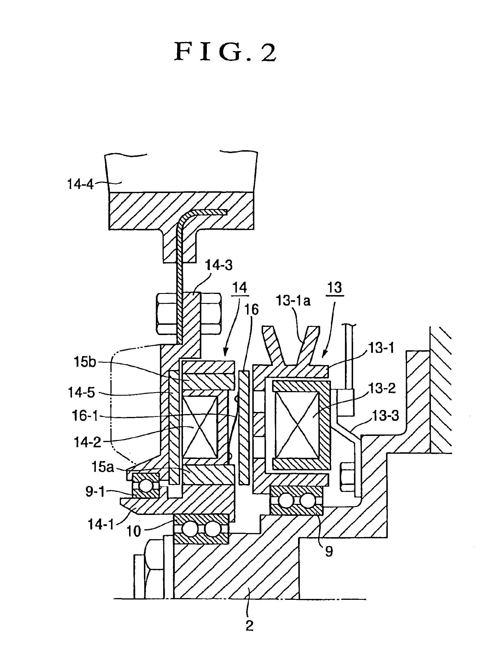
[0018]In FIGS. 1 to 5, reference numerals 1, 11 and 2 respectively designate an input shaft, an output shaft and a fixing shaft. Reference numerals 3, 13 designate electromagnetic clutches. Reference numerals 4, 14 designate magnet couplings. Reference numerals 5, 15a, 15b designate magnetic loop elements. Reference numerals 6, 16 designate armatures.

[0019]The magnet type clutch device shown in FIG. 1 has a structure in which the electromagnetic clutch 3 is attached to the input shaft 1 and the magnet coupling 4 is attached to the output shaft 11, and the electromagnetic clutch 3 and the magnet coupling 4 are surrounded by a case 18 rotatably supported by the input shaft 1 and the output shaft 11 through bearing devices 7, 17. The above electromagnetic clutch 3 is constructed by a clutch rotor 3-1 fixed to the input shaft 1, and a magnetizing coil 3-2 fixed to the case 18 within this rotor. On the other hand, the magnet coupling 4 is constructed by a permanent magnet rotating body 4...


PUM


Abstract

The invention provides a magnet type clutch device or a magnet type fan clutch device able to arbitrarily change the rotation speed of a fan by switching and controlling the directions of magnetic fluxes of a permanent magnet and an electromagnetic clutch. The magnet type clutch device or the magnet type fan clutch device constructed by integrating the electromagnetic clutch and a magnet coupling using the permanent magnet is characterized in that a magnetic loop element is assembled into a permanent magnet rotating body and the rotation speed of the fan, etc. can be changed by switching and controlling the magnetic flux direction of the electromagnetic clutch.

Description

BACKGROUND OF THE INVENTION[0001]1. Field of the Invention[0002]The present invention relates to a magnet type clutch device or a magnet type fan clutch device, etc. for a variable torque clutch of a transmission device for general industry, and a magnet type clutch device or a magnet type fan clutch device, etc. of low noises for controlling the rotation of a cooling fan applied to an internal combustion engine for a vehicle.[0003]2. Description of Related Art[0004]The magnet type fan clutch device constructed by integrating a magnet coupling and an electromagnetic clutch is already proposed as a fan clutch for controlling the rotation of the cooling fan (hereinafter simply called the fan) applied to the internal combustion engine for a vehicle, etc. (JP-A-2002-195303, etc.). In the magnet type fan clutch device of this kind, the magnet coupling and the electromagnetic clutch are combined with each other, and the fan is attached to the magnet coupling side. Concretely, for example,...

Claims


Application Information

Patent Timeline
IPC IPC(8): F16D27/00F16D27/01F16D27/12
CPCF16D27/01F04D25/026F16D27/12
Inventor INOUE, HIROSHISHIOZAKI, KEN
Owner USUI KOKUSAI SANGYO KAISHA LTD
Why Eureka
Try Eureka