Cavitation mixer

a cavitation mixer and mixer technology, applied in the direction of flow mixers, mixers, transportation and packaging, etc., can solve the problems of difficult to avoid, device effects only relatively poor mixing of fiber-material suspension components, and the intensity of the cavitation field produced using the device described in u.s. pa

Inactive Publication Date: 2005-08-30
LOCHER MANFRED LORENZ
View PDF13 Cites 108 Cited by
  • Summary
  • Abstract
  • Description
  • Claims
  • Application Information

AI Technical Summary

Benefits of technology

[0043]According to a further advantageous configuration of the invention, the body which it is difficult for medium to flow around consists at least in part of an elastic, nonmetallic material or has a corresponding covering. This inherently prevents the cavitation fields from having any disruptive effect on the equipment.
[0044]According to a further advantageous configuration of the invention, part of the mass flow which is to be mixed or a certain component thereof can be introduced directly into the through-flow chamber via a correspondingly designed holder and a correspondingly designed body which it is difficult for medium to flow around, in each case having corresponding hollow spaces which pass all the way through. In this way, the supercavitation field or its mixing action can once again be influenced in a controlled way, in particular according to the type of components which are to be mixed, in such a manner that an optimum mixing action is achieved.
[0045]According to a further advantageous configuration of the invention, both the body which it is difficult for medium to flow around and the mass flow in the through-flow chamber can be acted on by ultrasound. By way of example, this allows the body which it is difficult for medium to flow around to be set in vibration, which can intensify the formation of the cavitation fields and / or the mixing action thereof. Accordingly, applying ultrasound to the mass flow makes it possible to effect additional ultrasound cavitation and to intensify the cavitation fields which have already been generated by the body which it is difficult for medium to flow around itself and / or the mixing action thereof.

Problems solved by technology

Even slightly beforehand, the static pressure falls below the vapor pressure of the liquid, which is a few hundred Pa, and cavitation occurs, in particular, if microscopic air bubbles are already present as nuclei, which is difficult to avoid.
Therefore, this device effects only relatively poor mixing of the components of the fiber-material suspension with regard to the homogeneity (particle size) and long-term stability of the dispersion produced.
The intensity of the cavitation field produced using the device described in U.S. Pat. No. 3,834,982 is too low for mixing or dispersing phases which are difficult to mix or disperse.
However, the body which it is difficult for medium to flow around as a whole is arranged at a fixed location in a through-flow passage which, moreover, has a constant circular cross section in the region of the body which it is difficult for medium to flow around and as seen in the direction of flow.

Method used


Image

  • Cavitation mixer
  • Cavitation mixer
  • Cavitation mixer

Examples


first embodiment

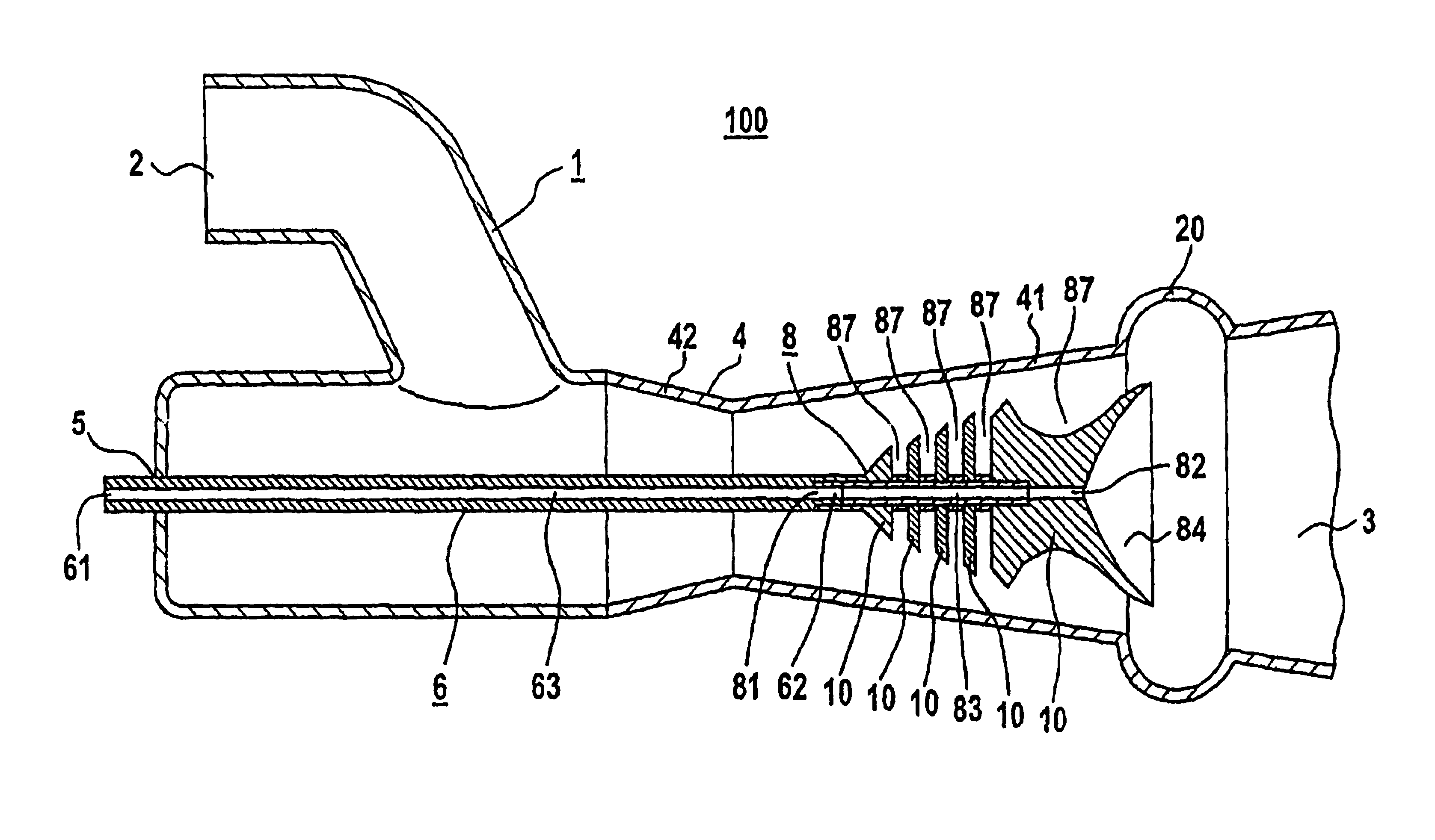
[0063]The housing 1 furthermore comprises a through-flow chamber 4 and a body 8 which is arranged therein by means of a holder 6 and which it is difficult for medium to flow around. In the case of the first embodiment, the holder 6 is designed and arranged in such a way that it projects into the housing 1 through a further opening 5 in the housing, in such a manner that the body 8 which it is difficult for medium to flow around is positioned in the through-flow chamber 4.

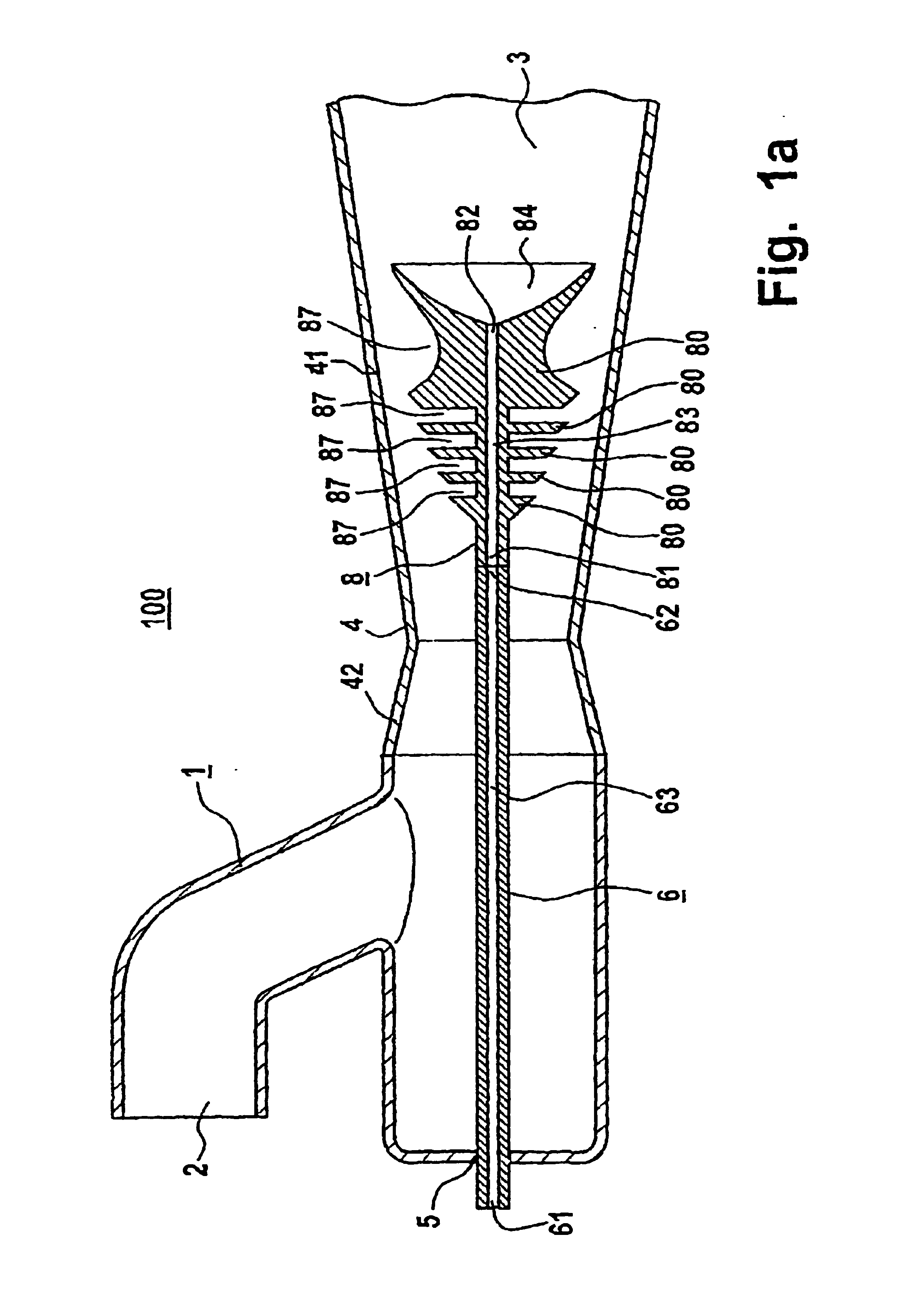
[0064]In the embodiment which is diagrammatically depicted in FIG. 1a, the through-flow chamber 4, the body 8 which it is difficult for medium to flow around and the holder 6 each comprise a rotationally symmetrical body, which bodies are arranged in such a way that their axes of symmetry coincide, i.e. are identical to the center axis of the through-flow chamber 4.

[0065]In particular, in FIG. 1a the holder 6 substantially comprises a hollow bar, i.e. has a hollow space 63 which passes all the way through and has an...

second embodiment

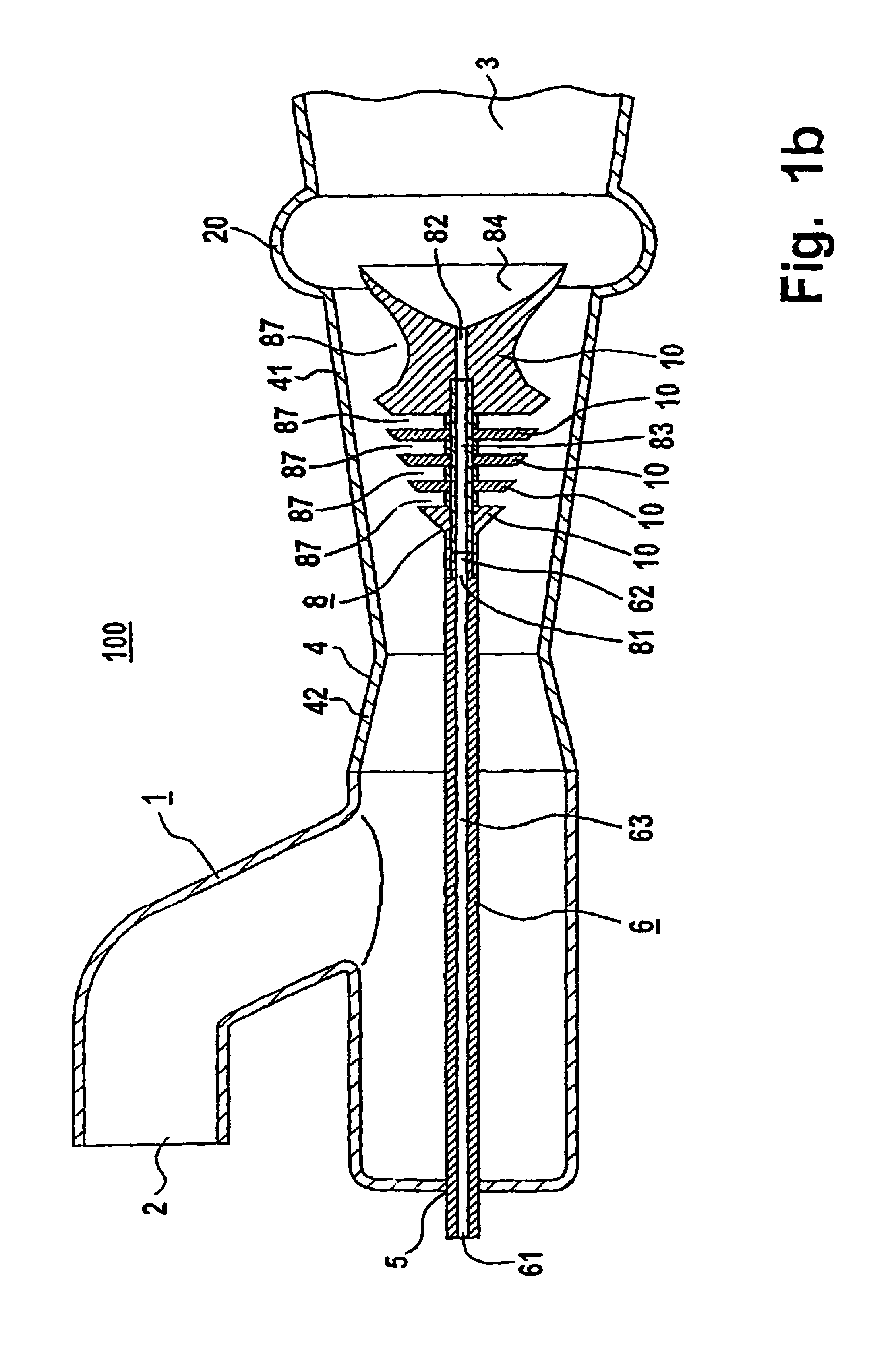
[0074]FIG. 1b shows a diagrammatic cross-sectional view, in the longitudinal direction of a supercavitation mixer 100 in accordance with a second exemplary embodiment of the invention, which represents a modification to the first exemplary embodiment shown in FIG. 1a. In particular, the invention differs from the first by dint of only two modifications.

[0075]The first modification relates to the body 8 which it is difficult for medium to flow around and which in the second embodiment is designed in such a way that each of its subregions 80 which it is difficult for medium to flow around and which is in the form of a truncated cone is designed as a partial body 10. Accordingly, the last two—as seen in the direction of flow—subregions 80, which it is difficult for medium to flow around, of the first embodiment are now designed as a single partial body 10. The spaces 87 through which medium can flow, between the subregions 80 or partial bodies 10 which it is difficult for medium to flo...


PUM


Abstract

A device for mixing the components of a mass flow flowing through it, provides a particularly homogeneous mixture with any desired long-term stability, even if components which are generally immiscible or can only be mixed with very great difficulty are being mixed. The device has a body (8), which it is difficult for medium to flow around, arranged in a through-flow chamber (4), this body being arranged at least partially in a part of the through-flow chamber (4) which widens in the direction of flow, so that the cavitation action and mixing action of the supercavitation field generated by the body (8) which it is difficult for medium to flow around is significantly reinforced.

Description

BACKGROUND OF THE INVENTION[0001]1. Field of the Invention[0002]The invention relates to a device for mixing the components of a mass flow flowing through it, in which the components may, in particular, be in solid, liquid or gas form by means of a hydrodynamic supercavitation field, in order to generate a mixture, in particular an emulsion or a suspension.[0003]2. Description of Related Art[0004]If what is known as the static pressure in a liquid flowing in, as a result of a flow constriction, locally falls below the vapor pressure, cavitation occurs, i.e. vapor-filled gas bubbles, which are also known as cavitation bubbles, are formed in the liquid. If the static pressure then increases again and exceeds the vapor pressure, these gas bubbles collapse implosively (practically at the speed of sound).[0005]This mechanism of hydrodynamically generated cavitation is covered by the Bernoulli-equation. According to this equation, it is generally the case (cf. “Gerthsen Physik”, Helmut Vo...

Claims


Application Information

Patent Timeline
Patent Type & Authority Patents(United States)
IPC IPC(8): B01F5/06B01F5/04B01F5/02B01J19/10
CPCB01F5/0256B01F5/0415B01F5/0652B01F5/0656B01F5/0451B01F25/23B01F25/3121B01F25/3131B01F25/4335B01F25/434
Inventor SCHUELER, ROLF
Owner LOCHER MANFRED LORENZ
Why Eureka
Try Eureka