Thin-film magnetic head, method of manufacturing the same, head gimbal assembly, and hard disk drive

Active Publication Date: 2012-07-05
HEADWAY TECH INC +1
View PDF3 Cites 12 Cited by
  • Summary
  • Abstract
  • Description
  • Claims
  • Application Information

AI Technical Summary

Benefits of technology

[0018]As described above, it has been difficult in the conventional PMR to reduce the electric resistance of the thin-film coil within the restriction range of RWS without increasing the magnetic path length.
[0019]The present invention is made to solve the above problem, and it is an object to reduce the electric resistance of a thin-film coil

Problems solved by technology

Therefore, if a part of the ABS protrudes, the

Method used


Image

  • Thin-film magnetic head, method of manufacturing the same, head gimbal assembly, and hard disk drive
  • Thin-film magnetic head, method of manufacturing the same, head gimbal assembly, and hard disk drive
  • Thin-film magnetic head, method of manufacturing the same, head gimbal assembly, and hard disk drive

Examples


first embodiment

[0092](Structures of Thin-Film Magnetic Head)

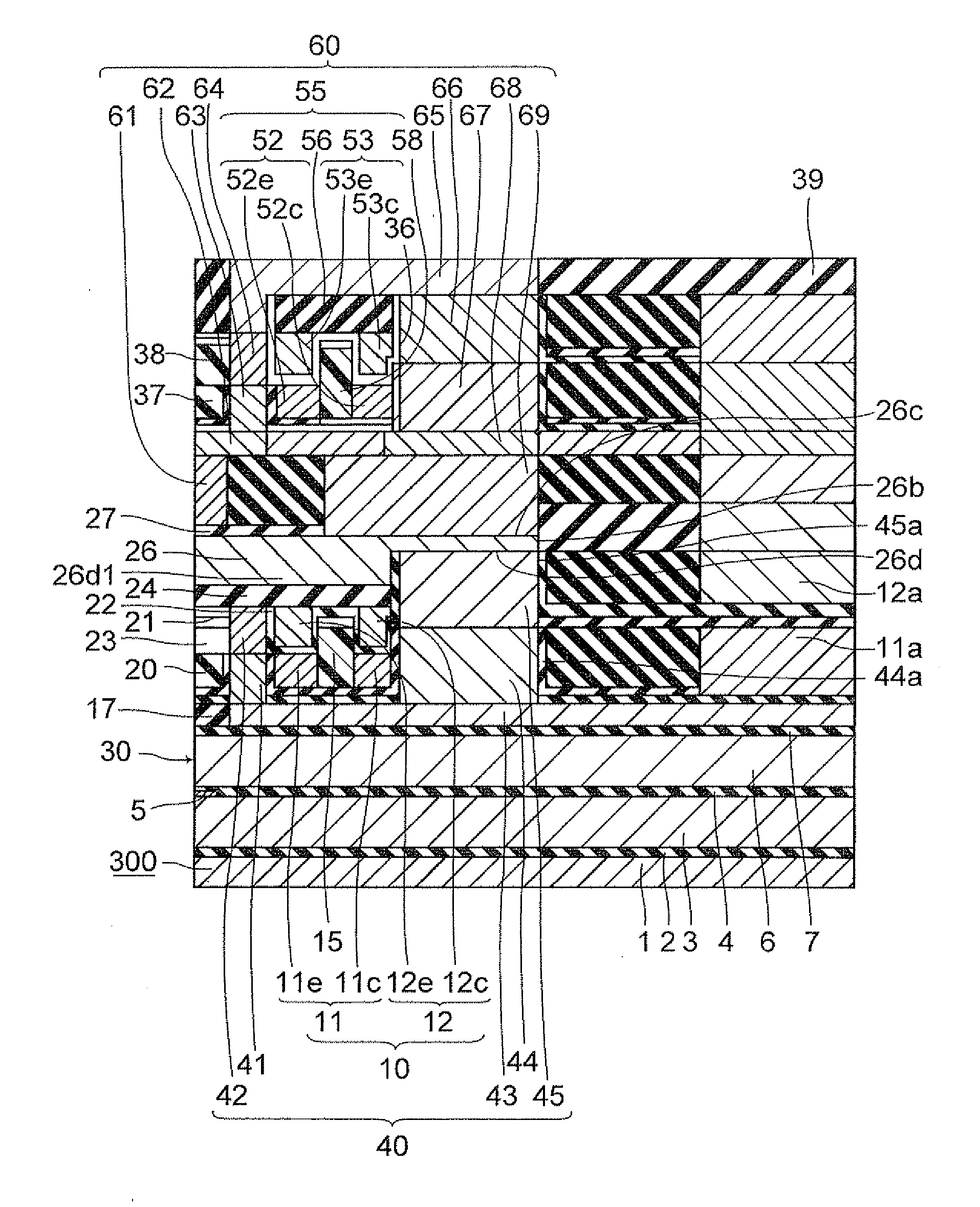
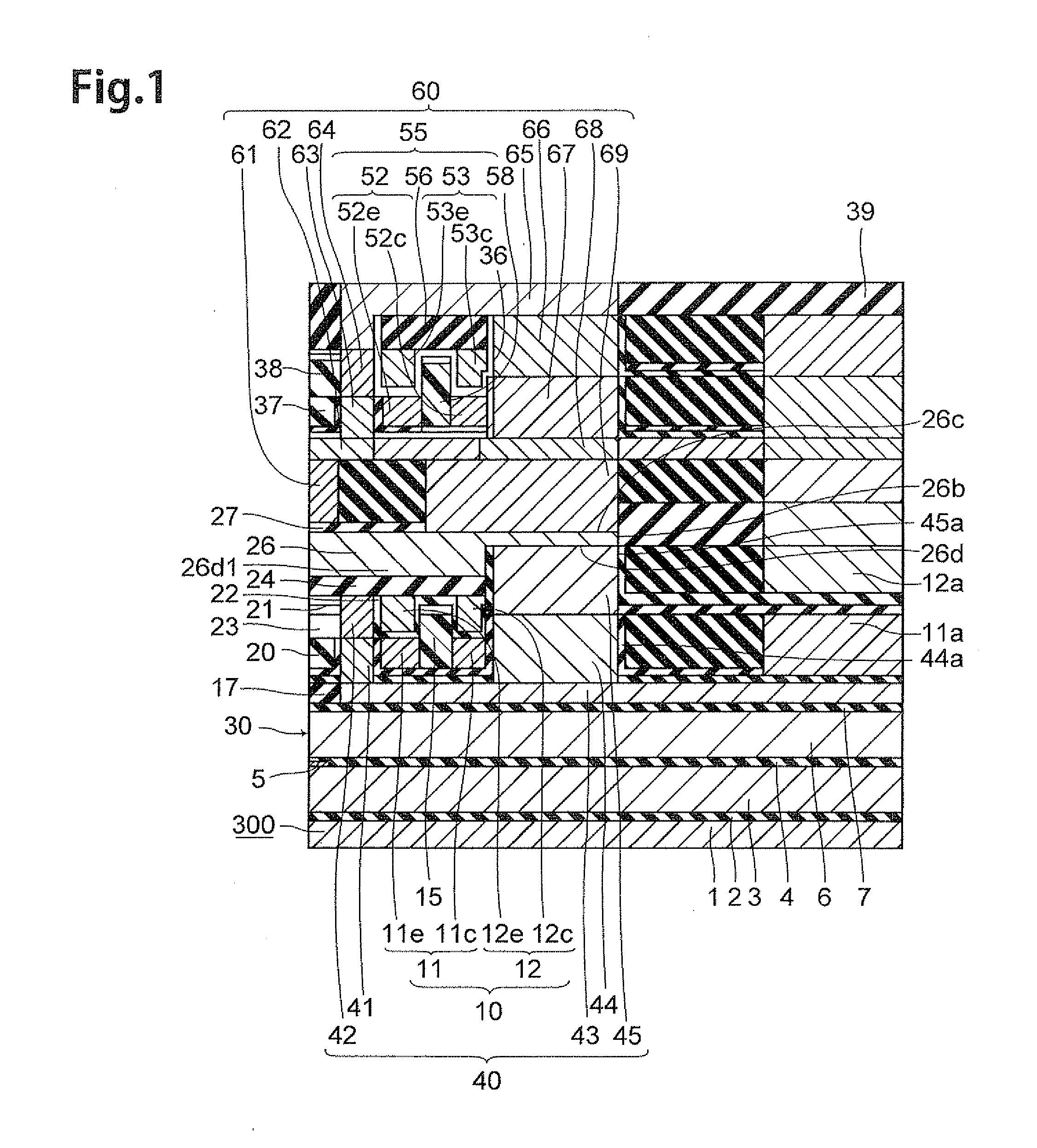
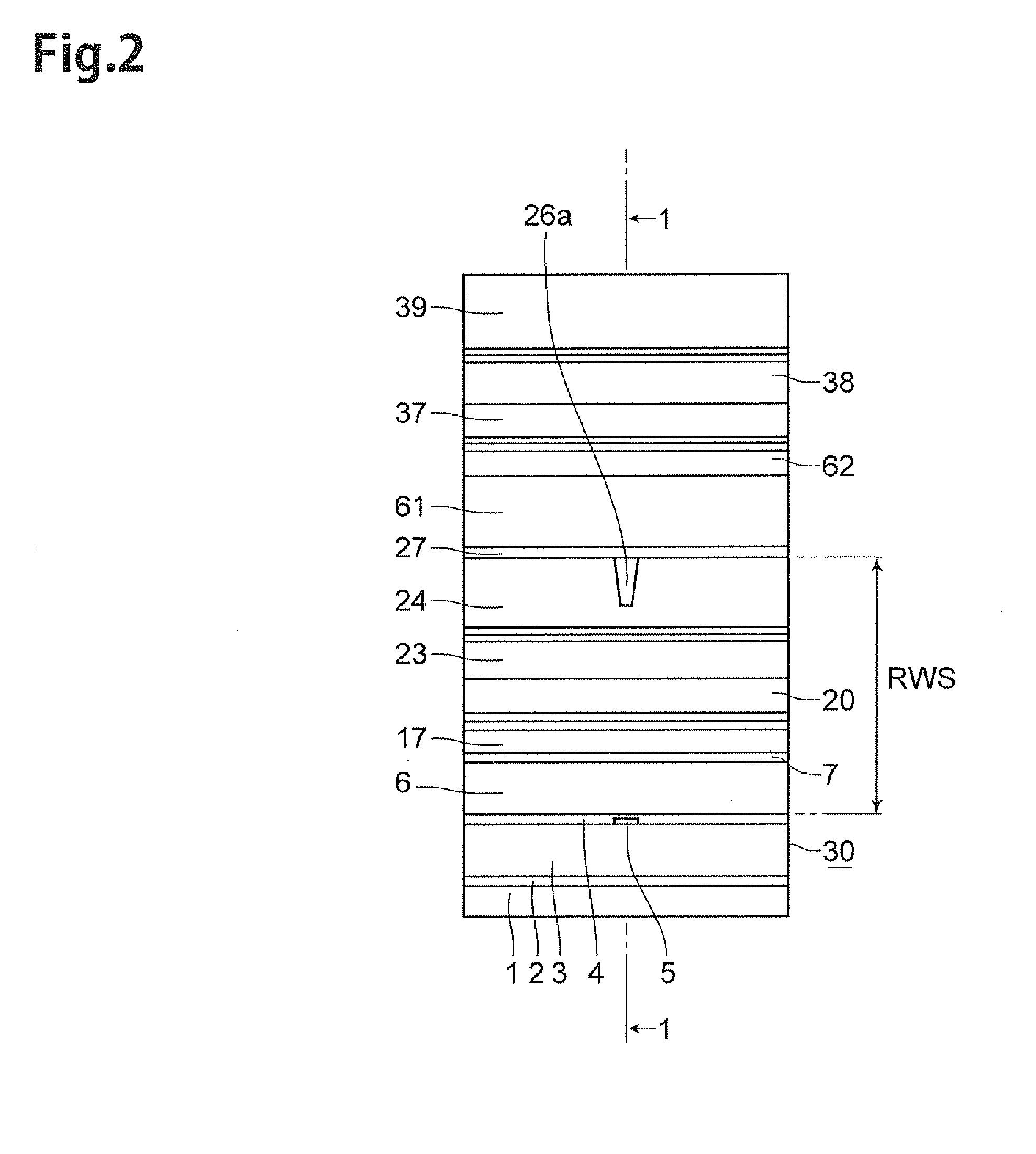
[0093]To begin with, the structure of a thin-film magnetic head of perpendicular magnetic recording type according to the first embodiment of the present invention will be explained with reference to FIG. 1 to FIG. 10. Here, FIG. 1 is a sectional view of the thin-film magnetic head 300 according to a first embodiment of the present invention taken along the line 1-1 of FIG. 2, along by a direction intersecting its air bearing surface (which will hereinafter be referred to as “ABS”), FIG. 2 is a front view illustrating the ABS 30 of the thin-film magnetic head 300. FIG. 3 is a plan view illustrating a first coil-layer 11. FIG. 4 is a plan view illustrating a second coil-layer 12. FIG. 5 is a plan view illustrating a principal part of the first coil-layer 11. FIG. 6 is a plan view illustrating a principal part of the second coil-layer 12 laid on the first coil-layer 11. FIG. 7 is a plan view illustrating the first coil-layer 11 with a diffe...

second embodiment

[0194]The structure of a thin-film magnetic head of perpendicular magnetic recording type according to the second embodiment of the present invention will now be explained with reference to FIG. 24 to FIG. 27. Here, FIG. 24 is a sectional view of the thin-film magnetic head 310 according to a second embodiment of the present invention corresponding to FIG. 1, along by a direction intersecting ABS 30. FIG. 25 is a plan view illustrating a first, second, third coil-layers 111, 112, 113. FIG. 26 is a plan view illustrating a principal part of the third coil-layer 113 laid on the first, second coil-layers 111, 112. FIG. 27 is a sectional view taken along the line 27-27 in FIG. 26.

[0195]As with the thin-film magnetic head 300, the thin-film magnetic head 310 comprises a substrate 1 and reproducing and recording heads laminated on the substrate 1, while having the ABS 30. Since the thin-film magnetic head 310 includes configurations identical to those of the thin-film magnetic head 300, c...

modified example

[0221]The above-described thin-film magnetic head 300, 310 have the lower thin-film coil 10, the lower thin-film coil 110 respectively. Both the lower thin-film coil 10 and the lower thin-film coil 110 have an overlapping structure in which a plurality of coil-layers overlies in the vertical direction. As described above, since the lower thin-film coil 10, the lower thin-film coil 110 have the overlapping structure, each turn part is arranged in a direction along with the ABS 30. Therefore, this allows the thin-film magnetic head 300, 310 to make the magnetic path length shorter as compared with a single story structure (for example, a conventional PMR 400) which each turn parts are arranged only along a direction intersecting the ABS 30.

[0222]However, the present invention is applicable to a thin-film magnetic head which has a thin-film coil 210, as illustrated in FIG. 28. The thin-film coil 210 has three turn parts 131, 132, 133. The three turn parts 131, 132, 133 are arranged in ...


PUM

PropertyMeasurementUnit
Thicknessaaaaaaaaaa
Magnetismaaaaaaaaaa

Abstract

A thin-film magnetic head is constructed such that a main magnetic pole layer, a write shield layer, a gap layer, and a thin-film coil are laminated on a substrate. The thin-film coil has a coil-layer. The coil-layer has a turn part arranged closer to an ABS than is a rear end part of the main magnetic pole layer farthest from the ABS. Regarding a substrate side coil-layer, arranged between the main magnetic pole layer and the substrate, of the coil-layer, a thickness of a non-corresponding magnetic pole part other than a magnetic pole corresponding part corresponding to an arrangement space of the main magnetic pole layer is larger than a thickness of the magnetic pole corresponding part.

Description

BACKGROUND[0001]1. Field of the Invention[0002]The present invention relates to a thin-film magnetic head which performs a magnetic recording action by a perpendicular recording scheme, a method of manufacturing the same, a head gimbal assembly, and a hard disk drive[0003]2. Related Background Art[0004]In recent years, hard disk drives have remarkably been improving their areal recording density. The areal recording density of hard disk drives has recently reached and is about to exceed 160 to 200 GB / platter in particular. In keeping with this trend, thin-film magnetic heads have been required to improve their performances.[0005]The thin-film magnetic heads can roughly be classified according to their recording schemes into those of longitudinal magnetic recording type and those of perpendicular magnetic recording type. The longitudinal magnetic recording scheme records data in a (longitudinal) direction within a recording surface of a hard disk (recording medium), while the perpend...

Claims


Application Information

Patent Timeline
IPC IPC(8): G11B5/10G11B5/48G11B5/127G11B5/17
CPCG11B5/1278Y10T29/49021G11B5/4853G11B5/3123
Inventor SASAKI, YOSHITAKAITO, HIROYUKISATO, KAZUKIIIJIMA, ATSUSHI
Owner HEADWAY TECH INC
Why Eureka
Try Eureka