Device for maintaining tension on lift cables

a technology for maintaining cable tension and lifting cables, which is applied in the direction of lifting, lifting vertical ships, hoisting equipment, etc., can solve the problems of cable protruding away from the winder, cabling problems remain constant, and two-part lines cannot use the tensioner, so as to prevent the crossing of lift cables and maintain cable tension.

Inactive Publication Date: 2005-08-30
BECKER GEORGE F
View PDF38 Cites 9 Cited by
  • Summary
  • Abstract
  • Description
  • Claims
  • Application Information

AI Technical Summary

Benefits of technology

[0012]A further object of the present invention is to maintain cable tension when the lower lifting beams become bouyant or subject to wave action.
[0014]Another object of the present invention is to be easily retrofittable to any new or used cable operated boat lift.
[0017]The present invention fulfills the above and other objects by providing a device for maintaining tension on lift cables which has a pulley and a weight or spring. The pulley will permit the cables to change direction while the weight or spring will be of sufficient size to maintain cable tension when the cable is attached to it. The cable is attached to the weight or spring and is adjustable. When the weight of the boat or cradle is removed from the boatlift, the weight or spring pulls down on the end of the cable, thereby maintaining tension. Because the boat or cradle weight is heavier than the weight attached to the machine, tension will still be maintained when the boat or cradle is replaced on the boatlift. In addition, the present invention can be used onto an existing boatlift by mounting it to the existing boatlift's top beam.

Problems solved by technology

However, two part line cannot use the tensioner as described above because the cable runs through a pulley on the lower members.
Thus, cabling problems remain a constant problem in the boatlift industry when using two part cables.
A significant drawback to using this product is that if the boatlift is allowed to run once the weight is off the cable, the cable tends to protrude away from the winder.
When the lift is restarted, however, the loop of cable which was formed tends to get caught under the cable keeper, often causing serious damage to the boatlift and the boat.
Although the weighted snatch blocks will maintain proper cable tension, the overall length of the device and its attachments severely limits the height the boat can be raised to, making the device extremely undesirable to many boaters.

Method used


Image

  • Device for maintaining tension on lift cables
  • Device for maintaining tension on lift cables
  • Device for maintaining tension on lift cables

Examples


Embodiment Construction

[0024]Listed numerically below with reference to the drawings are terms used to describe features of this invention. These terms and numbers assigned to them designate the same features throughout this description.

[0025]

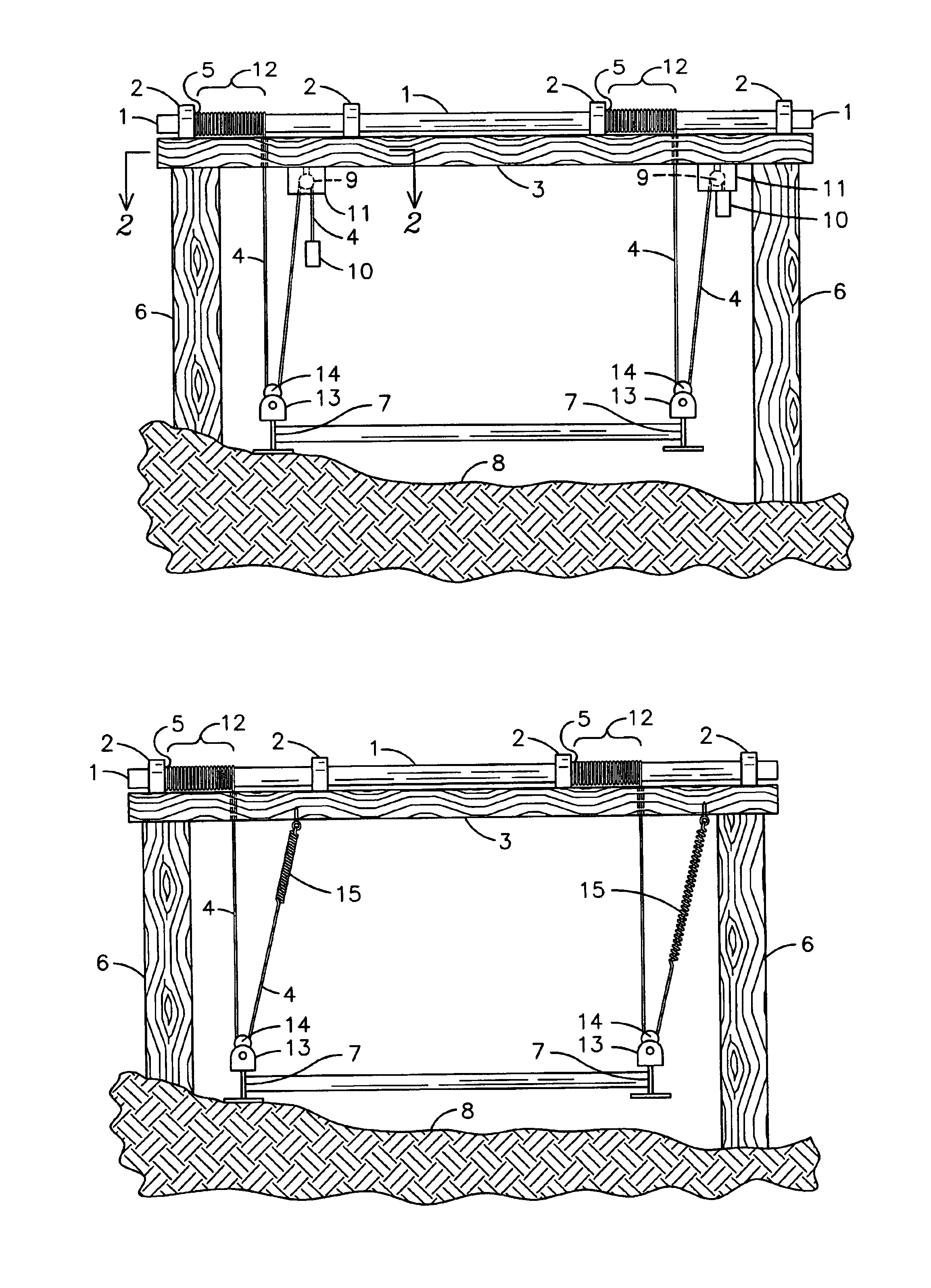
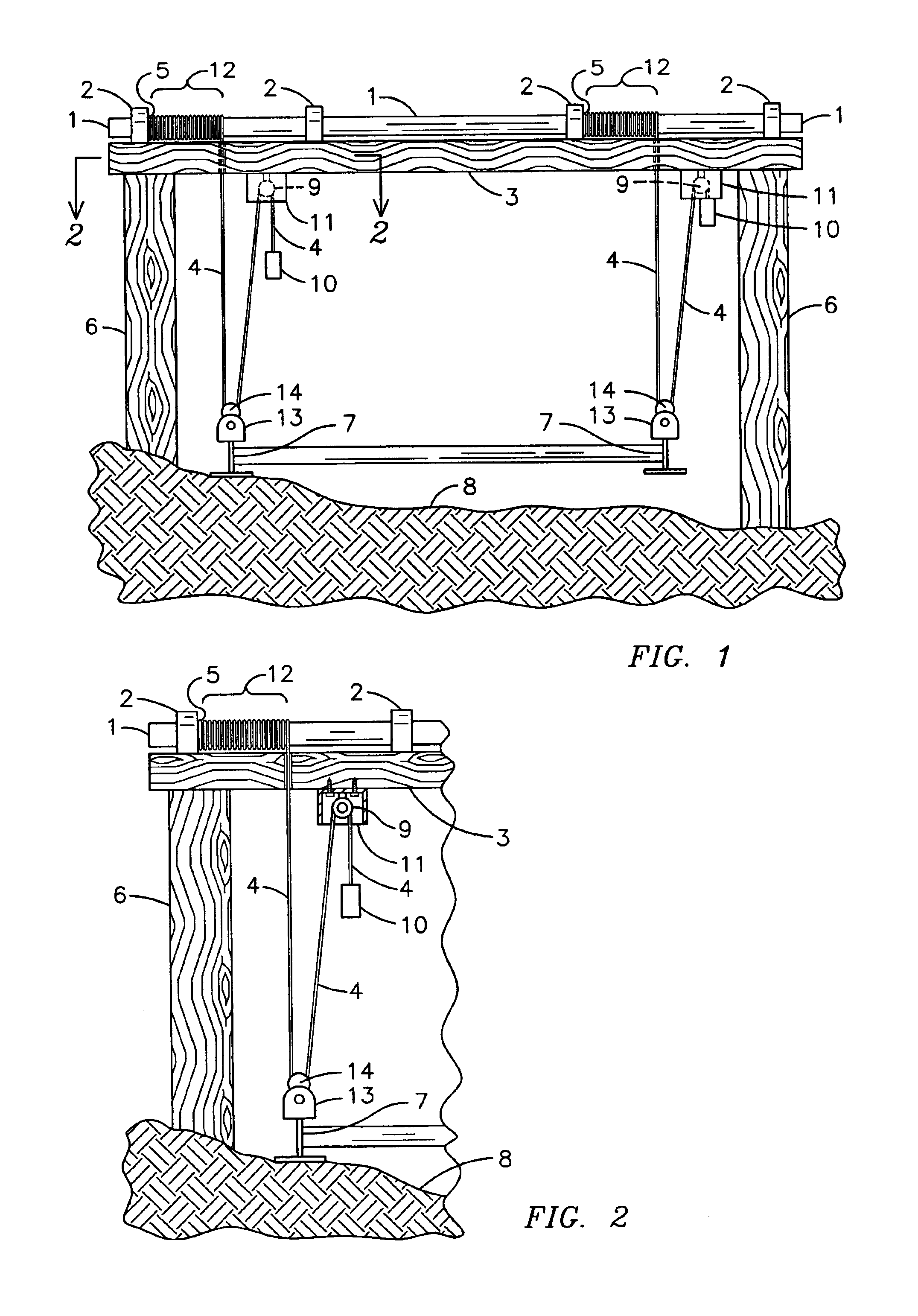
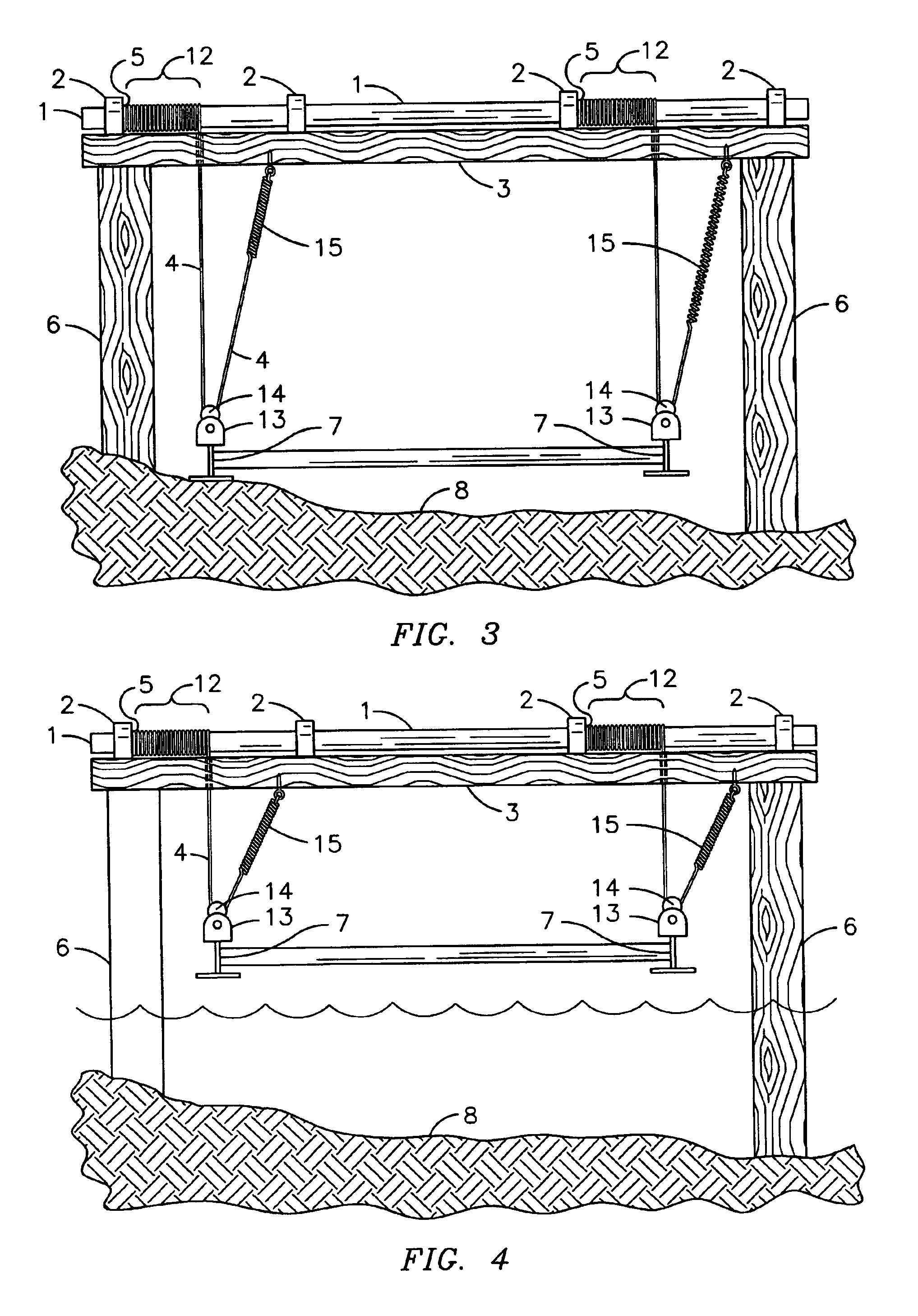
1.winder bar2.driveshaft bearing3.top beam4.cable5.tag end of cable6.vertical piling7.cradle beam8.bottom9.pulley10.weight11.stop12.winch spool13.cradle14.windlass15.spring

[0026]With reference to FIG. 1, a side view of the present invention installed on a boatlift where the tension means applied is a weight 10. Although one end of the cradle beam 7 is resting on the bottom and the other end of the cradle beam 7 is suspended, tension on the cables 4 is maintained at both ends by using a weight 10. The stationary top beam 3 of the boatlift is supported by vertical pilings 6. The winderbar 1 is attached to the top beam 3 by using driveshaft bearings 2. The tag ends of a cable 5 are attached to the winderbar 1 so that when the winderbar 1 rotates, a winch spool 12 is cre...


PUM


Abstract

A device for preventing the tangling or crossing of lift cables by maintaining the tension on the lift cables. When the tension is removed from lift cables (4) by placing a boat in a water body, the cables (4) become slack and can cross and / or tangle at a winderbar (1), which greatly reduces the life of the cables (4) and can cause serious damage to boatlift and boat. The present invention applies a tensioning means to the cables (4) by utilizing a weight (10) and pulley (9) or a spring (15) attached to an end of the lift cable (4). Lift cables (4) are first attached at one end to the winderbar (1). The cables (4) are then fed through the cradle (13). When using the weight (10) and pulley (4) system, the cables (4) are placed over a pulley (9) so that the weight (10) attached to the opposite end of the cable (4) maintains tension on the cables (4). The spring (15) tension means attaches the tag end of the cable (5) to the windbar (1) and the opposite end of the cable (4) is attached to a spring (15). The spring (15) is then affixed to a stationary object, such as a boatlift top beam (3) in order to maintain tension on the cables (4).

Description

CROSS REFERENCE TO RELATED APPLICATION[0001]This application claims the benefit of U.S. Provisional Application No. 60 / 407,826, filed Sep. 3, 2002.BACKGROUND OF THE INVENTION[0002]This invention relates to winch cables, and more particularly, a device for maintaining the tension on lift cables to prevent cable entanglement.[0003]In lifting devices, such as boatlifts, a lift cable is wound around a drum which is being rotated by a self-locking gear reduction unit. Thus, the drum effectively becomes a winch spool. Ideally, the cable should wind around the drum evenly without crossing or tangling, which can only be accomplished by maintaining cable tension. The proper winding of the cables is very important for two primary reasons: 1) cross or tangled cables significantly shorten cable life and 2) cross or tangled cables may cut themselves, thereby dropping the load. Thus, it is necessary to maintain tension on the cables.[0004]Typically there are two different cable routes used in the...

Claims


Application Information

Patent Timeline
Patent Type & Authority Patents(United States)
IPC IPC(8): B63C3/00B63C3/06B66D1/52B66D1/28B66F7/00
CPCB63C3/06B66D1/52B66F7/00
Inventor BECKER, GEORGE F.
Owner BECKER GEORGE F
Why Eureka
Try Eureka