Mushrooming expandable anchor

a technology of expandable anchors and mushroom, which is applied in the direction of deformable fasteners, screws, fastening means, etc., can solve the problems of affecting the installation ease and cost of parts, the top or backside of the material, and the use of backing nuts that are difficult or impossible to incorpora

Inactive Publication Date: 2005-08-30
ILLINOIS TOOL WORKS INC
View PDF66 Cites 66 Cited by
  • Summary
  • Abstract
  • Description
  • Claims
  • Application Information

AI Technical Summary

Benefits of technology

[0010]The mushrooming component has a tubular body with a short section of internal threads on one end and a square flat washer on the opposite end. The tubular portion of the mushrooming component has slits in the sides, and the sides are slightly bowed out to promote symmetrical collapse. The tube is collapsed by a treaded screw rotated within the tubular body pulling the internally threaded section downwards towards the washer at the base. The mushrooming anchor when collapsed has radially extended anchoring strips preventing extraction of the fastener from a hole drilled in the support through which the fastener extends.
[0017]The expandable anchor provides a known pull out strength which is necessary for building safety while providing an easy to install method having a fool proof, no stripping, overturning or over torquing feature thus preventing breakage of the fastener which may cause failure and increase construction costs.OBJECTS OF THE INVENTION
[0021]It is an object of the invention to provide a hanger, which is easy to install.
[0023]It is an object of the invention to provide easy access to a support point for easy installation of the hanger in confined spaces.

Problems solved by technology

Often times access to the top or backside of the material may be restricted making use of backing nuts difficult or impossible to incorporate.
These methods either use multiple installation steps with several parts being installed separately, or have limitations on the ease of installation and involve parts, which can be stripped, over torqued or otherwise compromised during or after installation.
Additionally, the space required by various mechanical systems incorporated in most buildings hinders and often prohibits the worker from easily reaching the support from which the hanger is to be attached.
This space limitation combined with multi-step processes for attaching the hanger such as drilling a hole, placing a back nut over the hole and turning in a bolt while balancing on a ladder is difficult, time consuming, dangerous and expensive.
Some methods used cannot guarantee the strength of the connection, due to base material limitations, thickness of the various building materials employed in today's building practices and installer error.

Method used


Image

  • Mushrooming expandable anchor
  • Mushrooming expandable anchor
  • Mushrooming expandable anchor

Examples


Embodiment Construction

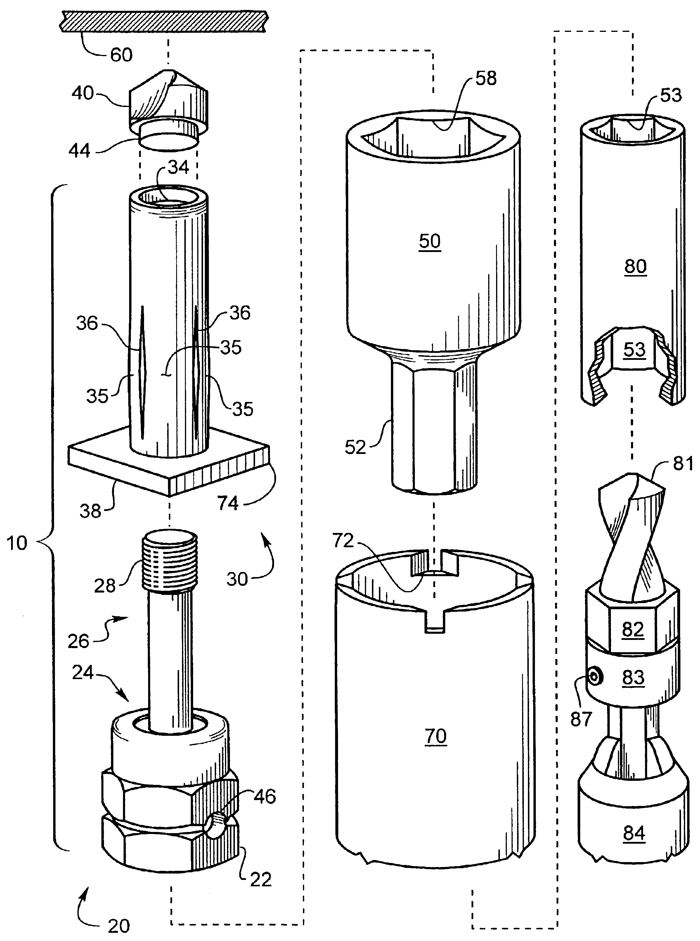
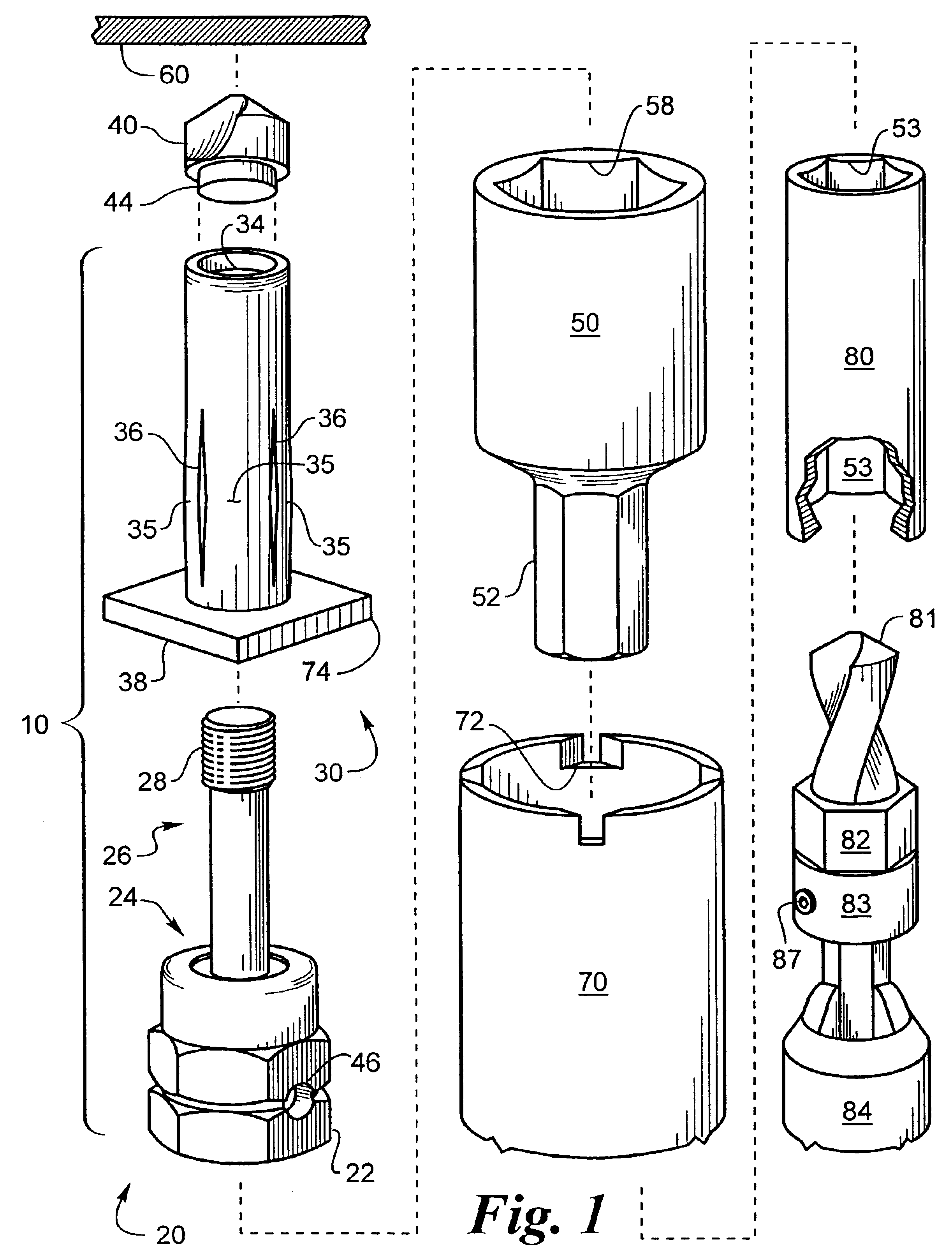
[0041]FIG. 1 shows the self-drilling screw with expandable anchor 10 unassembled. In a first embodiment the self-drilling screw having an expandable anchor 10 has three component parts. A hex head screw threaded component 20 similar to a SAMMY SUPER SCREW® sold by Speedy Products, Inc. owned by Illinois Tool Works, Inc. 3600 West Lake Avenue, Glenview, Ill. 60025-5811, a mushrooming component 30 similar to AVK Industrial Products A-R Series™ Threaded Insert, sold by AVK Industrial Products of Valencia, Calif. and a drill point 40. FIG. 1 also shows tools used to install the mushrooming expandable anchor 10. The tools include a socket 50 for turning the hex head screw 20, a sleeve tool 70 for engaging the expandable anchor 30, an internally broached drive shaft 80 for engaging the socket 50, a drive tool / adaptor 83 having a hex adaptor portion 82 to turn the above described assembly and adapt to drill bit 81, if a drill point 40 is not included in the assembly, and finally drill 84.

[...


PUM


Abstract

A self-anchoring fastening device for installation in supports for hanging pipes wires or other articles in ceilings is shaped for a socket to drive the device for an easy installation process. The device comprises a collapsible anchoring portion having radially expanding anchoring strips, which will not pull out of a hole drilled in a support. A drill drills a hole in a support and an expandable anchor is inserted through the hole. Threads internal to the expandable anchor cooperate with threads on a screw inserted therein to collapse the expandable anchor, providing anchoring strips over the hole such that the expandable anchor cannot be pulled out of the hole. A threaded portion of the base of the screw is suitable for attaching the article to be hung. The base may be a swivel head type. The drill may be on the expendable anchor assembly.

Description

[0001]This application claims benefit of U.S. Provisional application 60 / 370,487 filed Apr. 05, 2002.BACKGROUND OF THE INVENTION[0002]1. Field of the Invention[0003]This invention relates to self-expanding fasteners, which will not pull out of holes and more particularly for hanging pipe or other items inside buildings from overhead members.[0004]2. Description of the Related Art[0005]Plumbers, electricians, mechanical contractors, sprinkler fitters and maintenance personnel often have to hang pipe, conduit, cabling, ducting, light fixtures and various other items from structural supports such as ceilings, thin metal decking, roof decking, beams, Z purlin, bar joist or other truss materials.[0006]Specialty brackets must be employed or holes must be be drilled in the material and a mounting plate or bracket bolted in place with nuts, bolts, or screws to support a hanger therefrom. Often times access to the top or backside of the material may be restricted making use of backing nuts d...

Claims


Application Information

Patent Timeline
Patent Type & Authority Patents(United States)
IPC IPC(8): B25B27/00F16B13/06F16B29/00F16B13/00F16B35/06F16B35/04F16B13/04F16B13/13
CPCB25B27/0007F16B13/003F16B13/061F16B29/00F16B35/06B25B31/00
Inventor BODIN, RICHARD G.KOLODZIEJ, NORBERT K.
Owner ILLINOIS TOOL WORKS INC
Why Eureka
Try Eureka