Orthopedic splint

Inactive Publication Date: 2005-08-30
DAVIS PERRY H
View PDF31 Cites 76 Cited by
  • Summary
  • Abstract
  • Description
  • Claims
  • Application Information

AI Technical Summary

Benefits of technology

[0020]Another advantage of the present invention is the use of flexible structural support members.
[0021]Still another advantage of the present invention is the use of an adjustable hinge and locking mechanism for the flexible support members.
[0022]Yet another advantage of the present invention is the provision of an adjustable tensioning device.
[0023]Another advantage of the present inven

Problems solved by technology

Neurological impairment, physical trauma, surgery or prolonged immobility frequently results in loss of range of motion due to contraction of the muscles, tendons and ligaments of the limbs or digits known collectively as “soft tissue”.
Soft tissue contraction can result in loss of range of motion of the limb in flexion or extension.
If the level of force or onset rate at which the force is applied is too great, soft tissue may be stressed beyond the intended plastic phase and may be torn or otherwise damaged.
Misapplied force from a poorly designed or poorly fitting splint may force the limb outside the natural range of motion and de-stabilize the joint or cause permanent damage to the soft tissues.
Due to the labor intensive manufacturing process, custom orthotics are much more expensive than off-the-shelf splints and are not immedi

Method used


Image

  • Orthopedic splint
  • Orthopedic splint
  • Orthopedic splint

Examples


Example

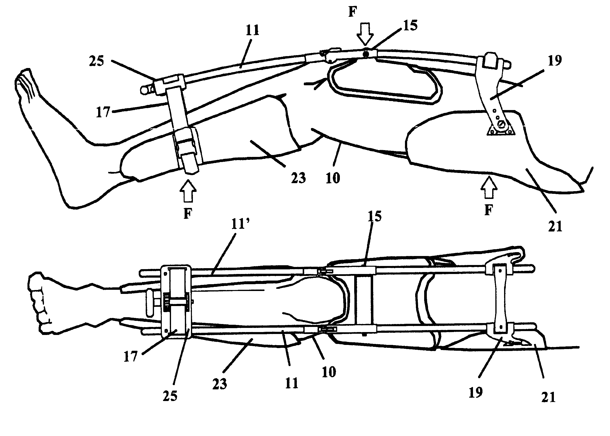
[0046]For descriptive clarity and continuity, illustrations depict the orthopedic splint of the present invention as applied to a lower limb of a human. Functionality and attributes of the present invention illustrated are not limited to a lower limb and apply equally in function and use to other limbs, extremities and digits of the human body. Though the illustrations and description depict two flexible support members 11 and 11′, the invention is not limited to this structure. For example, one flexible support member may be used, however, two such members provide a more stable splint.

[0047]Referring now to FIGS. 6A and 6B, the splint device of the present invention comprises one or more flexible support members 11 and 11′ oriented superior to the surface of the limb or digit 10. The flexible support members 11 and 11′ attach to a fulcrum point 15 located superior and in proximity to the limb joint (e.g., knee in the illustrations), and when placed under tension transfer force F vi...


PUM


Abstract

An orthopedic splint for a patient having a limb including an upper limb, a lower limb, and a joint therebetween, and being useful for therapeutically stretching the soft tissue of the limb. The orthopedic splint includes a flexible support member having a distal end and a proximal end thereof. A first contact pad is rotatably attached to the proximal end of said flexible support member and is disposed for distributing load to the underside of the upper limb. A second support pad attached to the distal end of said flexible support member is disposed for distributing load to the underside of the lower limb; and, a third support pad is attached to a fulcrum disposed near the center of the flexible support member and being disposed for distributing load to the topside of the upper limb and in close proximity to said joint. Accordingly, the orthopedic splint provides therapeutic traction to the limb while placing the limb in a self-aligning suspension sling arrangement.

Description

CROSS REFERENCE TO RELATED APPLICATION[0001]This is a continuation application of Provisional Application No. 60 / 440,559, filed Jan. 16, 2003 by the same inventor hereof.FIELD OF THE INVENTION[0002]The present invention generally relates to orthopedic splints, and in particular to an improved orthopedic splint that is designed to prevent or reduce soft tissue contraction of the limbs or digits. The present invention provides an improved fit and function when compared with dynamic and static splint prior art made orthopedic splints.BACKGROUND OF THE INVENTION[0003]Neurological impairment, physical trauma, surgery or prolonged immobility frequently results in loss of range of motion due to contraction of the muscles, tendons and ligaments of the limbs or digits known collectively as “soft tissue”. Soft tissue contraction can result in loss of range of motion of the limb in flexion or extension. Rehabilitation efforts to reduce or stretch such contractions usually involve extensive phy...

Claims


Application Information

Patent Timeline
IPC IPC(8): A61F5/01A61F5/058A61F5/04
CPCA61F5/0125A61F5/0585A61F2005/0158
Inventor DAVIS, PERRY H.
Owner DAVIS PERRY H
Why Eureka
Try Eureka