Air clamp stabilizer for continuous web materials

a technology of continuous web material and stabilizer, which is applied in the direction of lighting and heating equipment, printing equipment, instruments, etc., can solve the problems of air clamps that have a tendency to leave marks or otherwise damage the moving web, do not generate a sufficiently flat profile, and type air clamps

Active Publication Date: 2005-08-30
HONEYWELL INT INC
View PDF29 Cites 44 Cited by
  • Summary
  • Abstract
  • Description
  • Claims
  • Application Information

AI Technical Summary

Benefits of technology

[0015](b) directing a gas from the gas source through the slot so that a jet of gas moves through the opening and toward the lower portion whereby a low pressure field is estab

Problems solved by technology

These air clamps have a tendency to leave marks or otherwise damage the moving web.
Vortex-type air clamps provide adequate air bearing support but create a “sombrero-type” profile on the web material in the center of its effective region, thus they do not g

Method used


Image

  • Air clamp stabilizer for continuous web materials
  • Air clamp stabilizer for continuous web materials
  • Air clamp stabilizer for continuous web materials

Examples


example 1

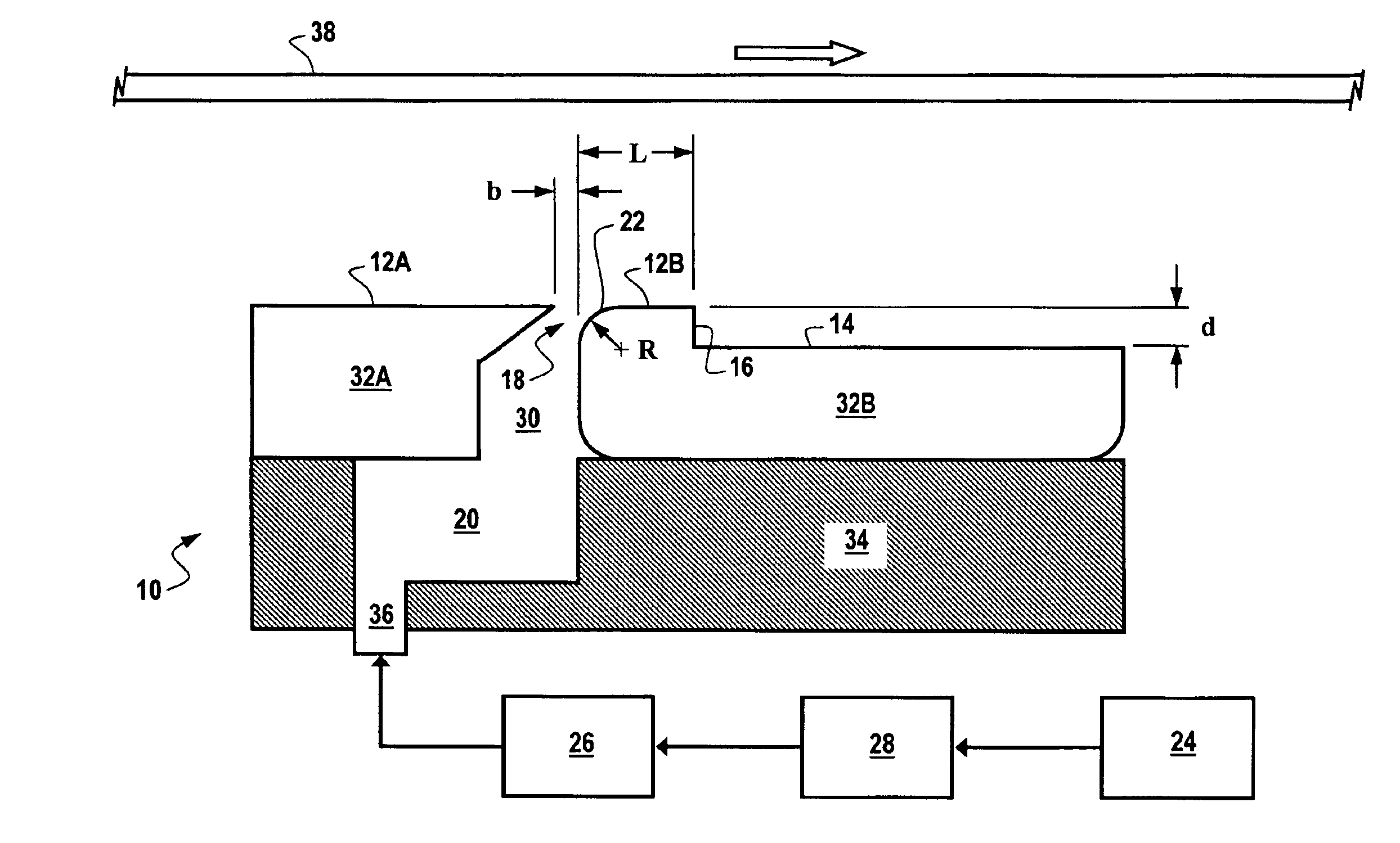
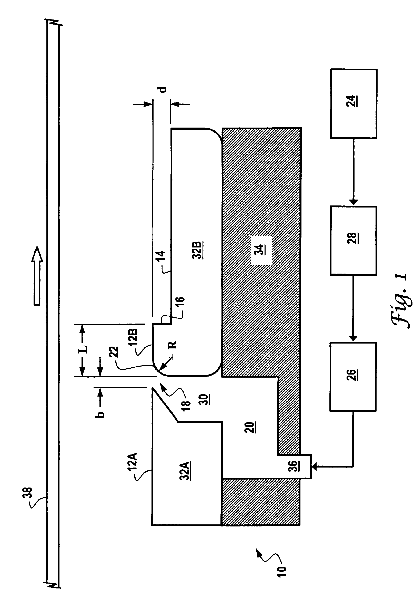
[0036]A stainless steel air clamp stabilizer having the configuration shown in FIG. 1 was fabricated and tested. Specifically, the stabilizer included a Coanda slot having a width (b) of 0.1 mm (0.004 in) and a curvature radius (R) of 1.6 mm (0.0625 in). In addition, the stabilizer had a backstep location (L) 3 mm downstream of the slot and a backstep depth (d) of 0.5 mm. Gas was supplied into plenum through three holes drilled into the underside of the device. The air clamp was employed to support a moving web of newsprint that was traveling at about 1790 m / min and had a water weight of 68 grams per square meter (gsm). The term “water weight” refers to the mass or weight of water per unit area of the paper.

[0037]The contour of the stabilizer surface was measured prior to operations. As depicted by the lower curve in FIG. 6, the vertical position of the upper surface was set at 500 μm above that of the lower surface. The lower curve highlights the presence of the Coanda slot located...

example 2

[0038]To demonstrate that incorporating a backstep downstream from the Coanda slot was the cause of the of improved paper sheet flatness, another stabilizer having the same Coanda slot as the stabilizer of Example 1 but without any backstep was tested. The conditions employed were the same as those for Example 1. As shown in FIG. 6, the paper profile has a pronounced minimum close to the location of the Coanda slot (indicated by the vertical hatched line) with a sharp increase downstream. The flat area that was obtained with the backstep (as shown in FIG. 5) is missing altogether. This shows the significance of the backstep in order to achieve sheet flatness.

example 3

[0039]The behavior of the air clamp stabilizer in response to changes in web speed was also studied. The procedure of Example 1 was repeated for newsprint traveling at 800 m / min. and 2690 m / min. FIG. 7 shows the paper sheet profiles 800 (curve A), 1790 (curve B), and 2690 m / min. (curve C). As is apparent, curve B and the stabilizer surface profile are identical to those of FIG. 5. The data show that the paper sheet profile downstream of the stabilizer is basically independent of the paper speed. Again the stabilized flat areas extend over 10 mm and have slopes of less than 0.1 degrees at all three paper speeds.


PUM


Abstract

A device for non-contact support of a continuous moving web of material employs an air clamp stabilizer that includes a Coanda slot and a backstep that is located downstream of the direction of the airflow extending from the Coanda slot. This configuration permits a Coanda jet to expand and to create an additional suction force. Vortex formation may also occur which further contributes to the strength of the suction force. As the web passes the stabilizer, an area of the web material rides on an air bearing that is maintained above the stabilizer surface and downstream of the backstep.

Description

REFERENCE TO RELATED APPLICATION[0001]This application claims priority to U.S. Provisional Application Ser. No. 60 / 345,860 filed on Oct. 24, 2001.FIELD OF THE INVENTION[0002]The present invention relates to an air stabilizer apparatus for non-contact support of a moving, continuous web of material. The air stabilizer imparts a force on the continuous web thereby maintaining the web material in a relatively flat profile as the web passes over the air stabilizer. This permits accurate measurements of web properties at the flat profile. The apparatus is particularly suited for use in the manufacture and processing of paper products.BACKGROUND OF THE INVENTION[0003]In the art of making paper with modern high-speed machines, sheet properties must be continually monitored and controlled to assure sheet quality and to minimize the amount of finished product that is rejected. The sheet variables that are most often measured include basis weight, moisture content, and caliper, i.e., thicknes...

Claims


Application Information

Patent Timeline
IPC IPC(8): B65H23/24B65H20/14B65H23/04D21F1/42D21F5/00D21F5/18D21F1/00D21F7/00
CPCB65H20/14B65H23/24D21F1/42D21F5/187
Inventor MOELLER, STEFANAXELROD, STEVENLUIS, JENSON
Owner HONEYWELL INT INC
Why Eureka
Try Eureka