Apparatus for continuous cooling of electrical powered equipment

a technology of electrical power equipment and apparatus, which is applied in the direction of gaseous cathodes, electric apparatus casings/cabinets/drawers, instruments, etc., can solve the problems of affecting the cooling efficiency of electrical power equipment, and requiring heat removal, etc., to achieve the effect of reducing the overall cooling efficiency

Active Publication Date: 2005-08-30
TOSHIBA INT
View PDF3 Cites 34 Cited by
  • Summary
  • Abstract
  • Description
  • Claims
  • Application Information

AI Technical Summary

Benefits of technology

[0005]Aspects of the present invention provide the capability of continuously cooling powered equipment to recover quickly from a natural or man-made disaster. A diversity system and method of present invention reduces single points of failures within subject equipment to provide uninterrupted operations. Thus, features of the present invention reduce damage to powered equipment and reduce operational cost.
[0011]In another aspect, an articulated air baffling system includes movable baffles. These movable baffles serve to isolate the non-running motor / impeller from the air flow path, thus preventing any unwanted air recirculation which would reduce the overall cooling efficiency.

Problems solved by technology

Large power conversion apparatus, such as medium voltage drives, become hot during operation, and consequently the heat needs to be removed to keep the apparatus from overheating.
Overheating can cause significant damage to the conversion apparatus.
It may take many hours and numerous personnel to determine what kind of failure occurred.

Method used


Image

  • Apparatus for continuous cooling of electrical powered equipment
  • Apparatus for continuous cooling of electrical powered equipment
  • Apparatus for continuous cooling of electrical powered equipment

Examples


Embodiment Construction

[0022]The following detailed description is divided into sub-sections to assist the reader. The sub-sections include: Overview; Illustrative Fan Assembly; Illustrative Controller; and Control Process.

Overview

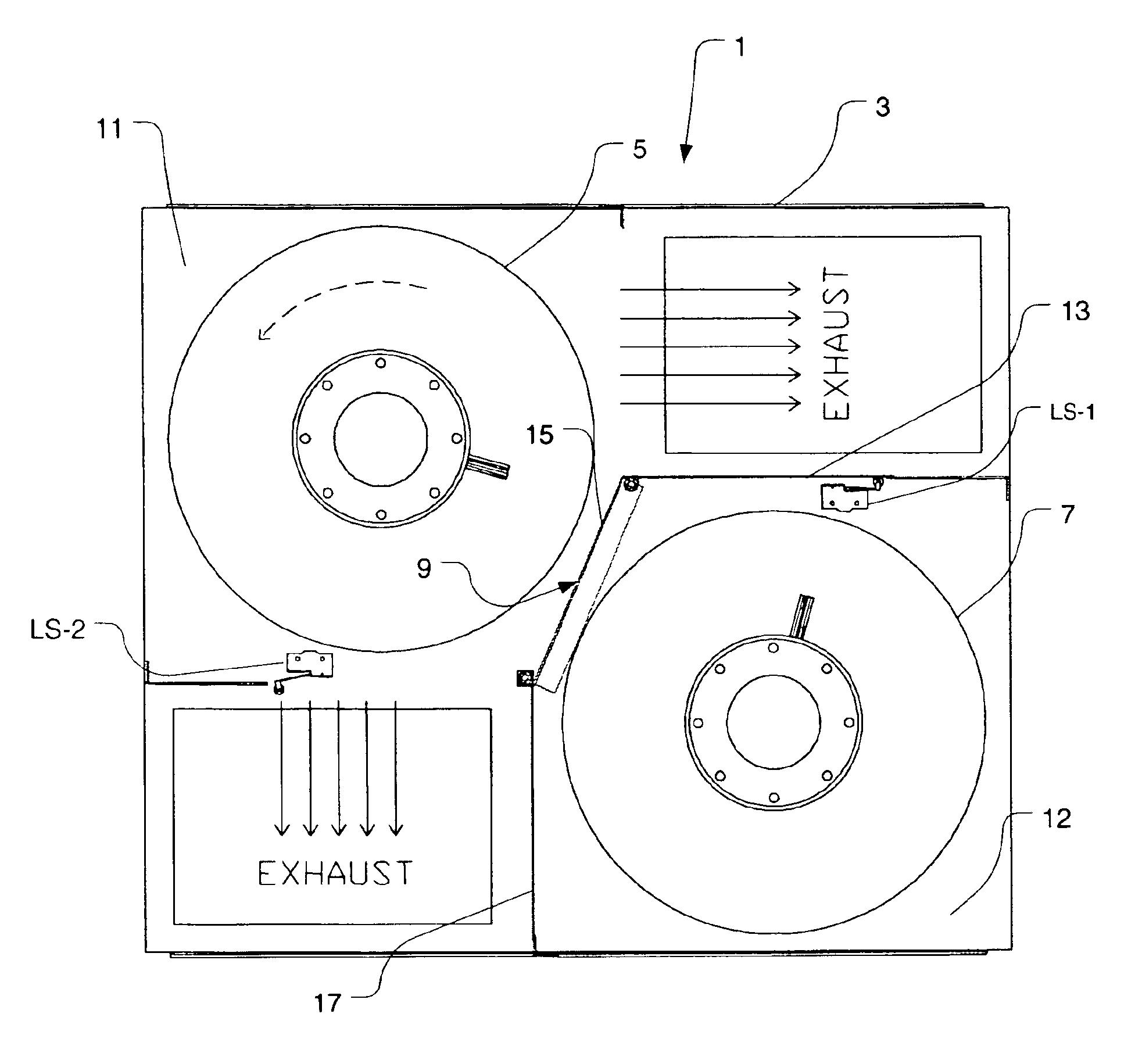
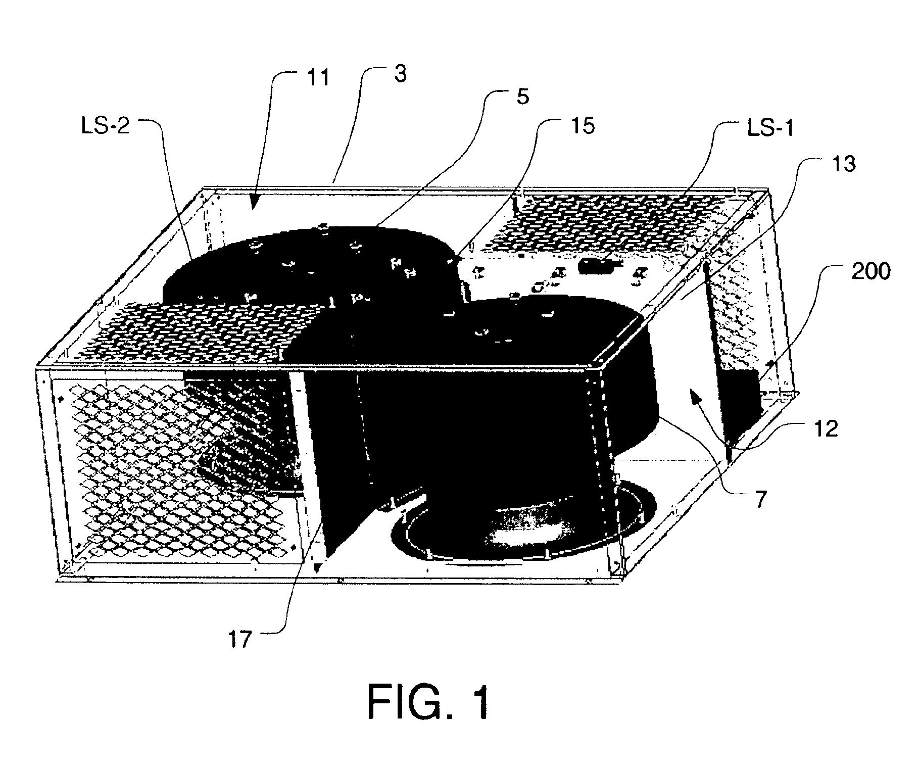
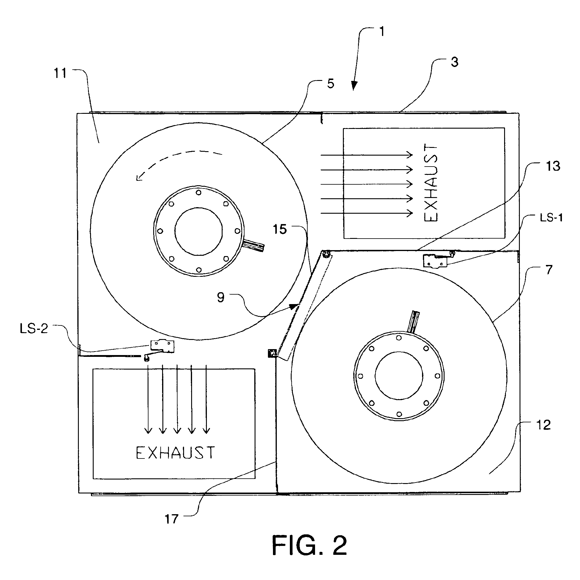
[0023]FIGS. 1-11 illustrate a system and method for fluidic cooling of electrical powered equipment according one or more features of the present invention. The term “fluidic cooling” pertains to removing heat by way of a dynamical fluid, such as air or other gas. In one aspect, the present invention provides the capability for continuously cooling powered equipment to recover quickly from a natural, man-made disaster, or other failure. In one aspect, autonomous control operations provided by the present invention allows for efficient operations to significantly reduce operational costs and prevent equipment damage. Reliance on standby maintenance support personnel for installation of cooling systems are eliminated with the continuity tools and systems of the present invention o...


PUM


Abstract

A fluidic cooling assembly for removing heat from electrical equipment includes operational diversity features in which multiple fluid moving devices are mounted in a single housing. The assembly may include a first fluid baffle and a second fluid baffle disposed within the housing so as to define a first and a second control compartment. A first fan and a second fan may be disposed within the first control compartment and the second control compartment, respectively. A first sensor and a second sensor may be configured to sense changes in operation of the first fluid moving device and the second fluid moving device, respectively; and a controller unit configured for receiving signals generated by the first sensor and the second sensor go as to the transmit control signals to the first fan and the second fan.

Description

FIELD OF THE INVENTION[0001]Aspects of the present invention are directed generally to an apparatus and method for fluidic cooling of electrical powered equipment. More particularly, aspects of the present invention relates to a fan assembly and method for cooling an electrical power conversion unit.BACKGROUND OF THE INVENTION[0002]Large power conversion apparatus, such as medium voltage drives, become hot during operation, and consequently the heat needs to be removed to keep the apparatus from overheating. Overheating can cause significant damage to the conversion apparatus. Transformers, rectifiers and power switching devices generate heat. Some systems have a fan to help remove the heat. In the case of a failure of the fan in conventional systems, the power conversion apparatus must be shut down before overheating occurs. It may take many hours and numerous personnel to determine what kind of failure occurred. This is important when considering the complex electrical system the ...

Claims


Application Information

Patent Timeline
Patent Type & Authority Patents(United States)
IPC IPC(8): H02G3/08H05K7/20H05K5/00
CPCH05K7/20572H05K7/207
Inventor KLEINECKE, JOHN D.WILLHOIT, TODD A.KELLEY, JOHN T.
Owner TOSHIBA INT
Why Eureka
Try Eureka