
Method and apparatus for examining fiber material traveling in a fiber processing machine

a fiber processing machine and fiber web technology, applied in the direction of geological measurements, instruments, safety devices for fiber treatment, etc., can solve the problems of inability to detect and determine the degree of achieve the effect of improving the degree of uniform detecting and determining the homogeneity of the fiber web

Inactive Publication Date: 2005-08-30
TRUETZSCHLER GMBH & CO KG
View PDF11 Cites 0 Cited by
  • Summary
  • Abstract
  • Description
  • Claims
  • Application Information

AI Technical Summary

Benefits of technology

[0006]It is an object of the invention to provide an improved method an apparatus of the above-outlined type which eliminates the discussed disadvantages and which, in particular, improves a detection and determination of the homogeneity of the fiber web, particularly the distribution and orientation of useful fibers and furthermore improves the degree of fiber web uniformity.
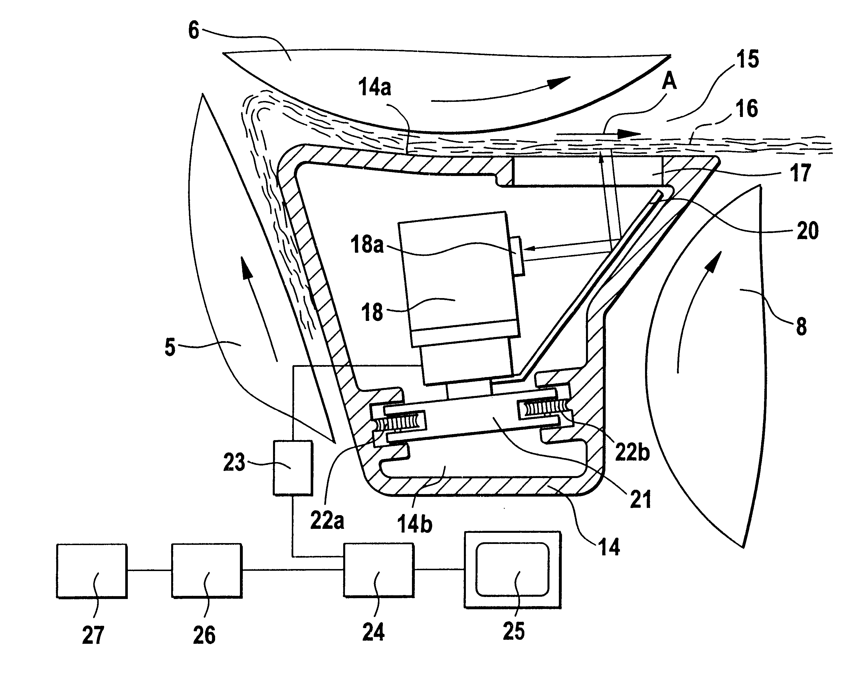
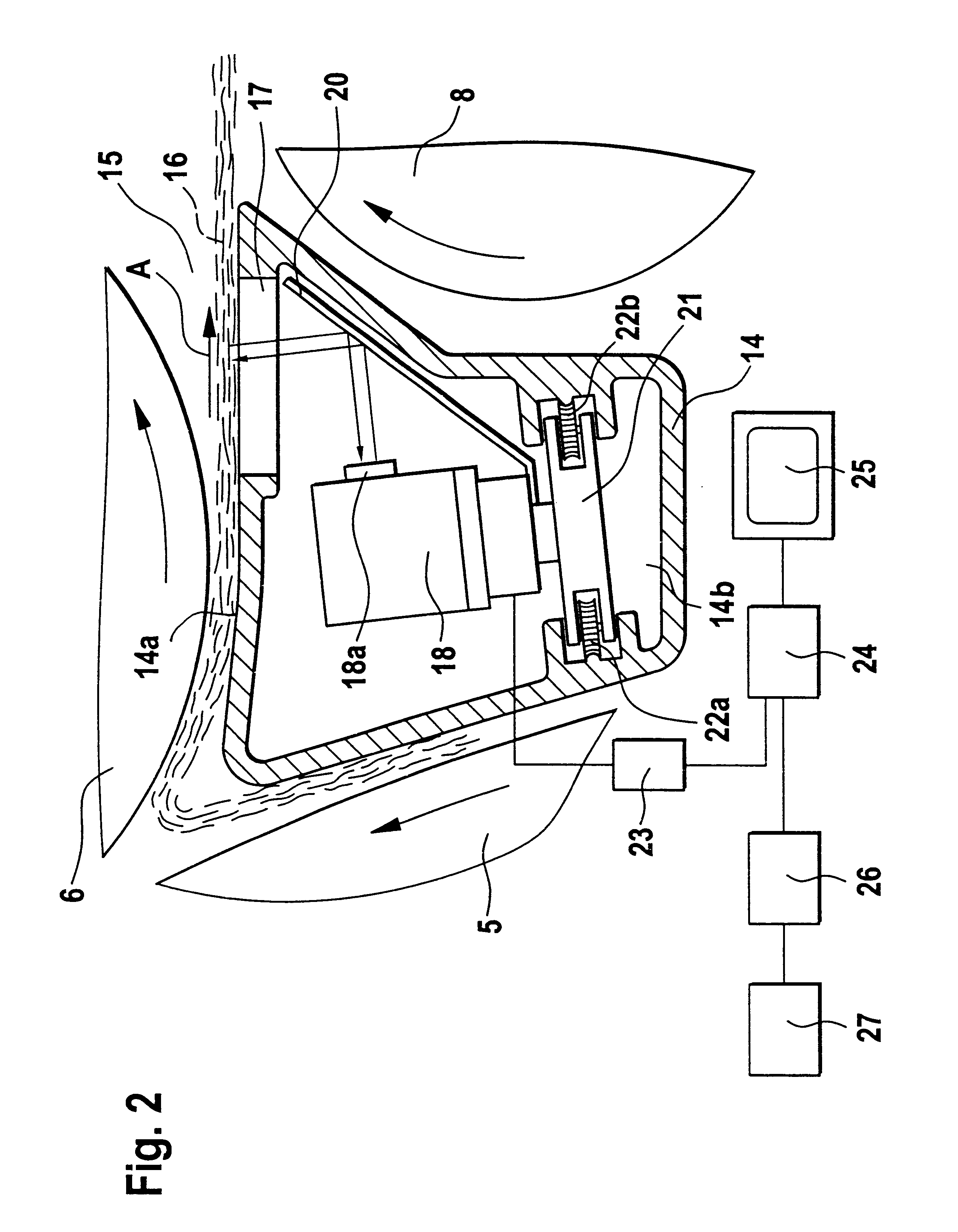
[0008]According to the invention, the useful fibers and voids, that is, the spaces (empty locations) between the useful fibers are detected and evaluated. From the ratio between the useful fibers and the empty locations per area unit the homogeneity and the web irregularity (cloudiness) is determined, whereby the distribution and orientation of the useful fibers in the fiber web are ascertained. The measuring values permit an image display and an optical and electronic evaluation. By examining the homogeneity, defects in the region of the roll clothings or an incorrect fiber feed may be detected and thus the quality of the produced fiber web may be improved. The homogeneity of the web produced by the carding machine or the roller card unit is automatically and continuously detected and evaluated so that by means of the machine control and setting members the processing of the fiber material may be affected. The greater the selected scanned surface area, the better the detectability of the distribution of the useful fibers.

Problems solved by technology

It is a disadvantage of the above-outlined conventional arrangement that a detection and determination of the degree of homogeneity of the fiber web is not feasible.

Method used


Image

  • Method and apparatus for examining fiber material traveling in a fiber processing machine
  • Method and apparatus for examining fiber material traveling in a fiber processing machine
  • Method and apparatus for examining fiber material traveling in a fiber processing machine

Examples


Embodiment Construction

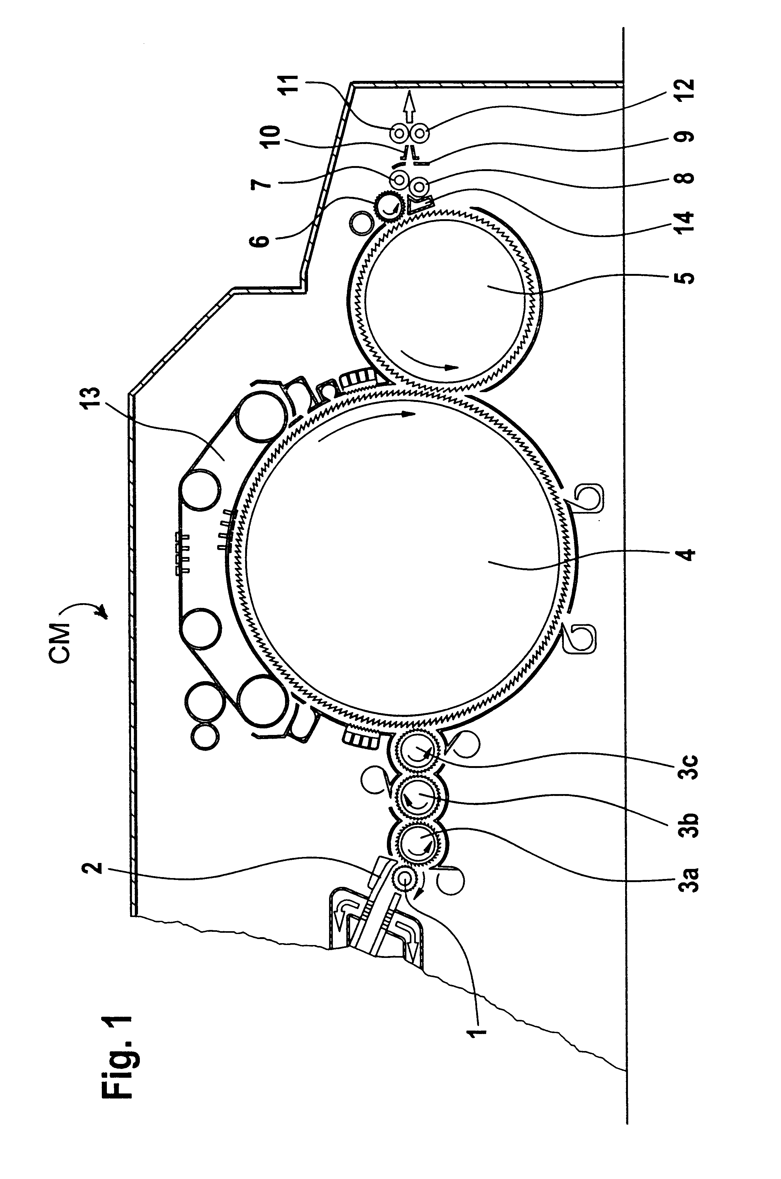
[0027]FIG. 1 illustrates a high performance carding machine CM which may be, for example, a DK 903 model manufactured by Trützschler GmbH & Co. KG, Mönchengladbach, Germany.

[0028]The carding machine CM has a feed roll 1, a feed table 2 cooperating with the feed roll, licker-ins 3a, 3b and 3c, a main carding cylinder 4, a doffer 5, a stripping roll 6, cooperating crushing rolls 7 and 8, a web guiding element 9, a web trumpet 10, cooperating pull-off rolls 11 and 12 and a traveling flats assembly 13. Underneath the stripping roll 6 a web supporting and guiding body 14 is provided. The upper crushing roll 7 is in a close proximity to the stripping roll 6. The direction of rotation of the main carding cylinder 4 and the rolls are shown by the curved arrows drawn thereinto.

[0029]Turning to FIG. 2, in the region 15 of the carding machine the fiber web 16 leaves the stripping roll 6 and advances, as indicated by the arrow A, toward the crushing rolls 7, 8 on the surface 14a of the supporti...


PUM


Abstract

An apparatus for evaluating a fiber web running in a card includes a camera for scanning the fiber web along a length and width portion thereof to detect useful fibers and empty locations in the fiber web and to generate signals representing the useful fibers and empty locations; and an evaluating device connected to the camera for determining a distribution of useful fibers per area unit in the fiber web from the signals.

Description

CROSS REFERENCE TO RELATED APPLICATION[0001]This application is a continuation of U.S. application Ser. No. 09 / 658,718 filed Sep. 11, 2000 now abandoned.[0002]This application claims the priority of German Application No. 199 43 079.9 filed Sep. 9, 1999, which is incorporated herein by reference.BACKGROUND OF THE INVENTION[0003]This invention relates to a method and an apparatus for examining a fiber web advanced in a fiber processing machine such as a card or a roller card unit. The material of the web is cotton, chemical fibers or the like. The fiber web has useful fibers with intermediate, empty spaces therebetween (hereafter also referred to as empty locations). The apparatus includes a measuring track for the fiber material. The measuring track is associated with a camera, such as a diode matrix camera which is connected with an evaluating device such as an image processing computer.[0004]German Offenlegungsschrift (application published without examination) 39 28 279 to which ...

Claims


Application Information

Patent Timeline
IPC IPC(8): D01G31/00G01N21/88G01N21/89
CPCD01G31/006G01N21/8915
Inventor HOSEL, FRITZ
Owner TRUETZSCHLER GMBH & CO KG
Learn More