Method for detecting and identifying defects in a laser beam weld seam

a laser beam and weld seam technology, applied in the direction of laser beam welding apparatus, instruments, material analysis, etc., can solve the problems of limiting the number of sensors, the way the signals are processed in the known welding monitoring system, and the precision and reliability required

Inactive Publication Date: 2005-08-30
AEROSPATIALE MATRA
View PDF12 Cites 97 Cited by
  • Summary
  • Abstract
  • Description
  • Claims
  • Application Information

AI Technical Summary

Benefits of technology

[0016]The object of the invention is a method enabling real-time, reliable and reproducible detection and identification of possible defects present in laser weld seams.

Problems solved by technology

They are totally inappropriate for materials of other types and particularly for alloys of titanium or aluminum used in other industries such as the aeronautical industry.
Furthermore, the means for processing the signals used in these known welding monitoring systems do not have the precision and reliability required in the context of the latter industry.
Otherwise the welding monitoring systems used today in the automotive industry use unwieldy sensors, placed in the immediate proximity of the welding head.
Such operations limit the number of sensors and consequently, the number of measurement signals available to assure the detection of defects.
However, it does not enable identification with certainty or entirely.
As in the above case, this system cannot detect, much less distinguish in a reliable manner all of the possible defects present in the welding seam.
Discrimination between the different types of defects is not reliably assured.

Method used


Image

  • Method for detecting and identifying defects in a laser beam weld seam
  • Method for detecting and identifying defects in a laser beam weld seam
  • Method for detecting and identifying defects in a laser beam weld seam

Examples


Embodiment Construction

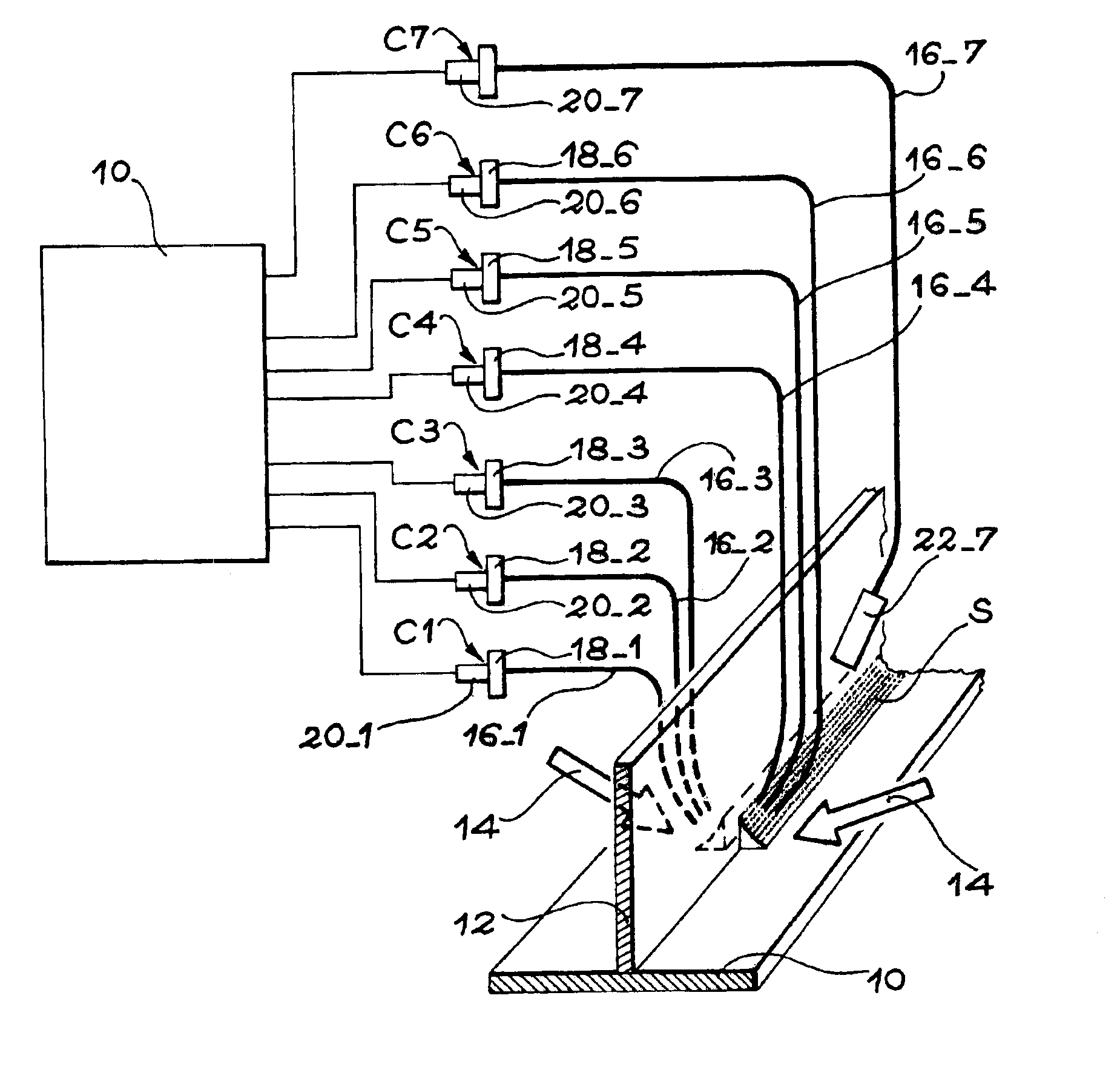
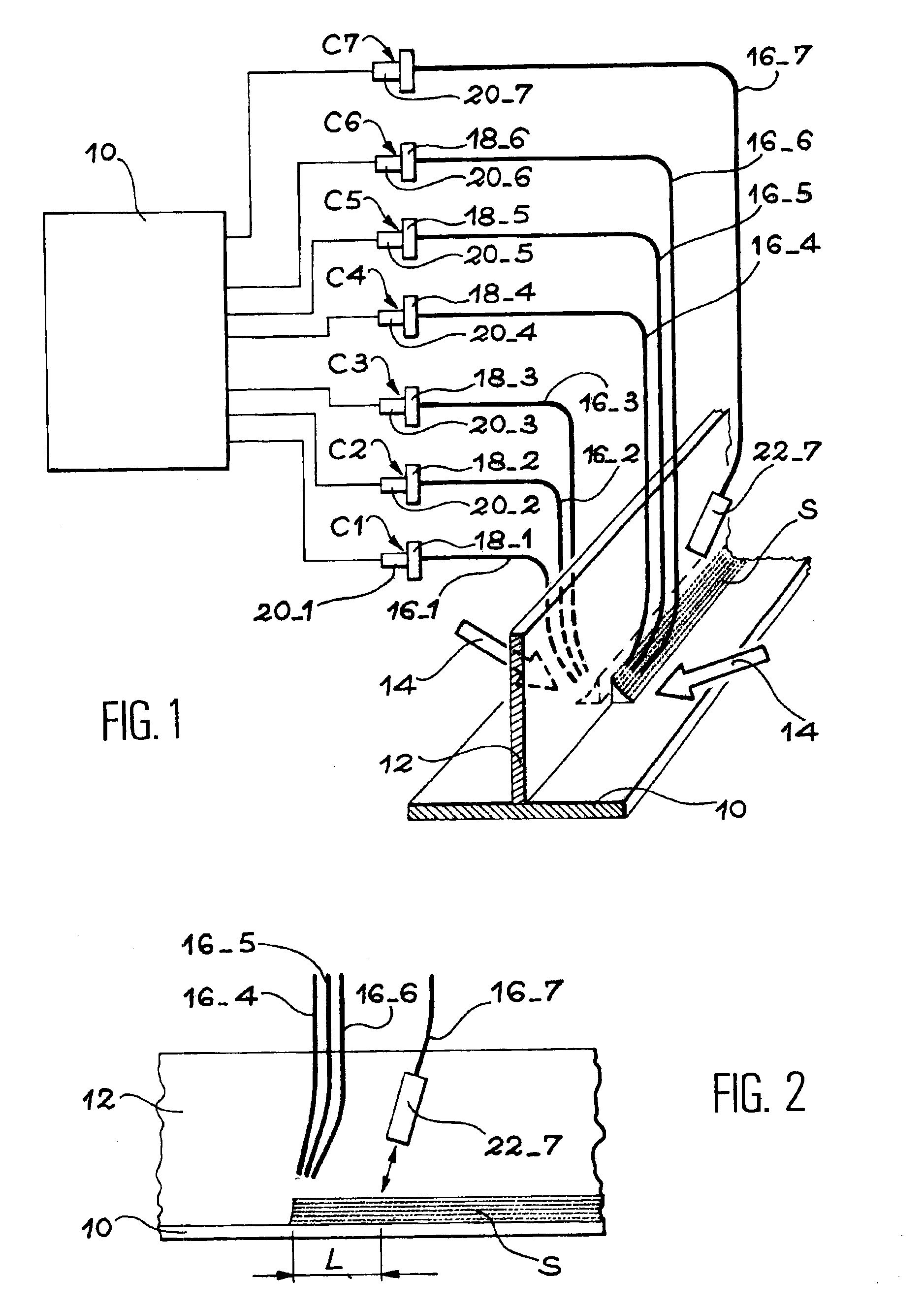
[0041]As represented schematically in FIG. 1, the invention relates to the real-time, non-destructive inspection of the quality of a welding realized between two pieces 10 and 12 using one or a plurality of lasers 14 (represented by the arrows in FIG. 1.). As illustrated by way of non-limiting example, the piece 10 can be a substantially flat or slightly curved metal plate and the piece 12 can be a stud that is to be welded onto the inside face of the metal plate 10 by means of two laser beams 14 disposed on either side of the stud 12. The invention, however, also relates to other types of assemblies such as edge-to-edge assembly of two metal plates, etc.

[0042]In other respects, the pieces 10 and 12, whose welding is to be inspected, are metallic pieces what can be made of different metals such as alloys of aluminum, alloys of titanium, inox steels, etc.

[0043]The laser(s) 14 used for welding together the pieces 10 and 12 can be comprised of any type of laser conventionally used in t...


PUM

PropertyMeasurementUnit
distanceaaaaaaaaaa
distanceaaaaaaaaaa
diameteraaaaaaaaaa

Abstract

A method for detection and identification of defects in a weld seam created using a laser beam.According to this method, at least two measurement signals are acquired in real time delivered by optical sensors (C1 to C6) detecting variations in luminous intensity of the plasma formed by the laser beam (14). These signals are then combined by applying a mathematical operation. The combined signal obtained is then compared to a predetermined threshold. Depending on the result of this comparison, a determination is made of the presence or absence of a defect corresponding to the operator used.

Description

TECHNICAL FIELD[0001]The invention relates to a procedure developed for non-destructively detecting, localizing and identifying in real time any defects present in weld seams made by one or a plurality of laser beams.[0002]More particularly, the invention relates to a method for detecting and identifying defects, which makes use of optical sensors sensitive to variations in luminous intensity of the plasma that forms in the region of the weld under the effects of the laser beam(s).[0003]The invention is applicable to welding of parts of any type of metal such as parts made of aluminum alloy, titanium alloy, inox steel, etc. In particular, it can be utilized to inspect edge-to-edge welding of two metal sheets, welding of a stud on a metal sheet (T-joint, double filet weld), etc.[0004]Further, the invention can be adapted to different welding configurations. Thus, it related to all types of welding using one or a plurality of lasers, YAG, CO2, etc. with or without filler material.[000...

Claims


Application Information

Patent Timeline
Patent Type & Authority Patents(United States)
IPC IPC(8): B23K26/00B23K26/02G01B11/04G01B11/08G01N21/00G01N21/84
CPCB23K1/0056B23K26/032B23K26/243B23K31/125B23K26/242
Inventor ESMILLER, BRUNO
Owner AEROSPATIALE MATRA
Why Eureka
Try Eureka