Rotation recording apparatus and method of inspection thereof

a recording apparatus and rotation technology, applied in the field of inspection methods, can solve the problems of inability to detect spes defects so accurately, and the linear relationship between displacement and output cannot be kept, so as to achieve the effect of efficiently detecting defects and errors

Inactive Publication Date: 2005-08-30
HITACHI GLOBAL STORAGE TECH NETHERLANDS BV
View PDF3 Cites 2 Cited by
  • Summary
  • Abstract
  • Description
  • Claims
  • Application Information

AI Technical Summary

Benefits of technology

[0009]It is an object of the present invention to detect defects and errors not only in the center of each track, but also at a boundary between tracks when data is written in a SAT. It is another object of the present invention to detect defects and errors efficiently.
[0011]Concretely, the test described above employs an additional method for enabling a write test to be done at a boundary line between tracks, where the SPES rate of change becomes very large with respect to a micro change of the C / D burst. Consequently, mainly C and D burst defects have come to be detected, thereby serious errors as described above can be avoided effectively. When a test pattern is written at a boundary between tracks at the outer periphery side of each track and an error is detected there while writing of the test pattern data is started at the outer periphery of a disk, tracks at both sides of the boundary are decided as defective. When no error is detected, the test pattern is written in the center of each track. When an error is detected in a track, only the track is decided as defective. The use of such the algorithm will thus make it more efficient to detect defective servo information.

Problems solved by technology

When the head moves from one track to another, however, the linear relations between both of the displacement and the MPES output cannot be kept as it is.
However, while this method can detect MPES defects accurately around the center of each track, it cannot detect any SPES defects so accurately.
When such a disorder occurs, it often causes a serious error, for example, sudden head movement for compensation and / or execution of write operation in a wrong track.

Method used


Image

  • Rotation recording apparatus and method of inspection thereof
  • Rotation recording apparatus and method of inspection thereof
  • Rotation recording apparatus and method of inspection thereof

Examples


Embodiment Construction

[0017]Hereunder, the preferred embodiment of the present invention will be described with reference to the accompanying drawings. It is to be understood, however, that changes and variations may be made without departing from the spirit or scope of the present invention. And, note that the same reference numerals will be given to the same elements throughout the embodiment.

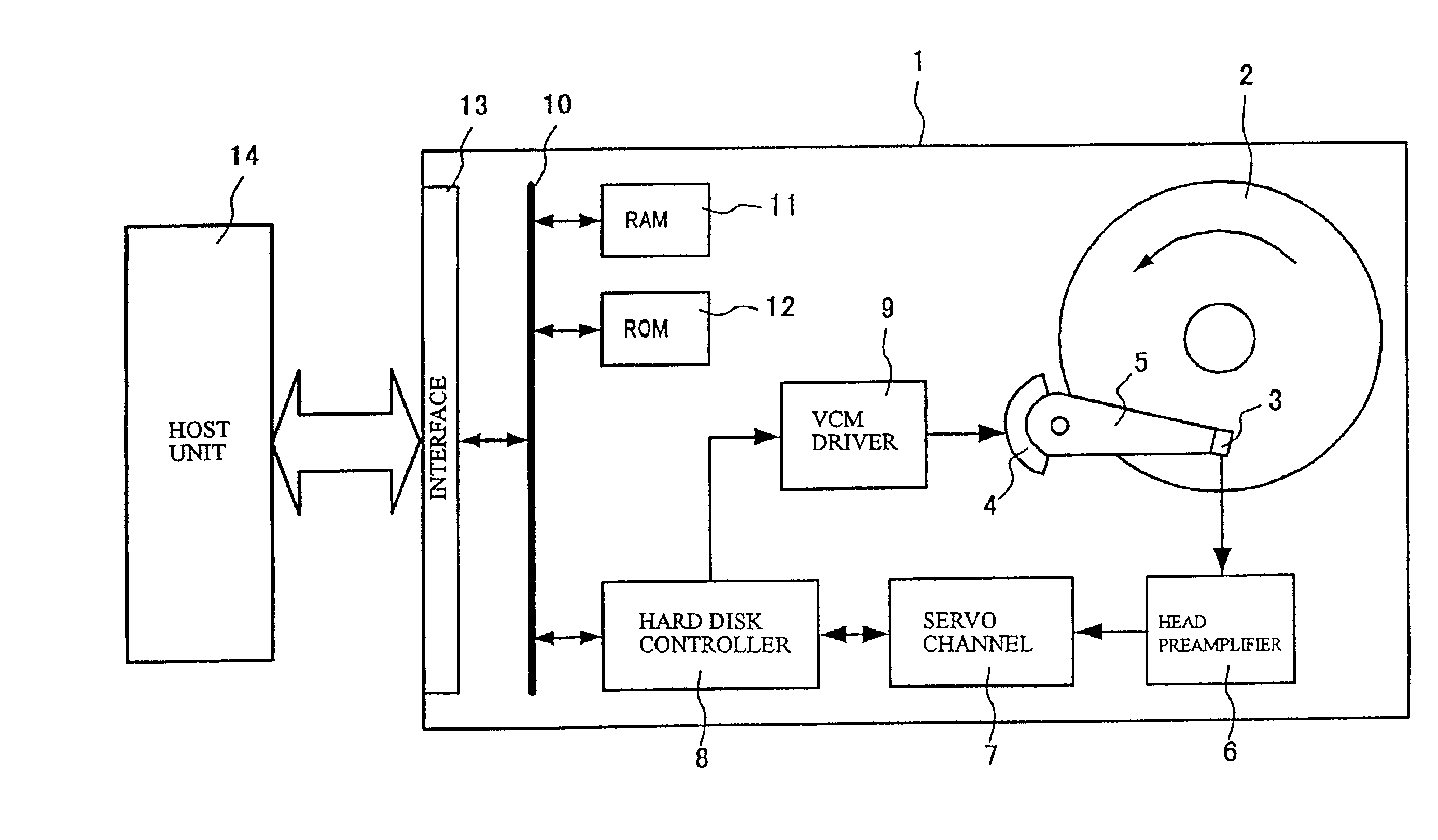
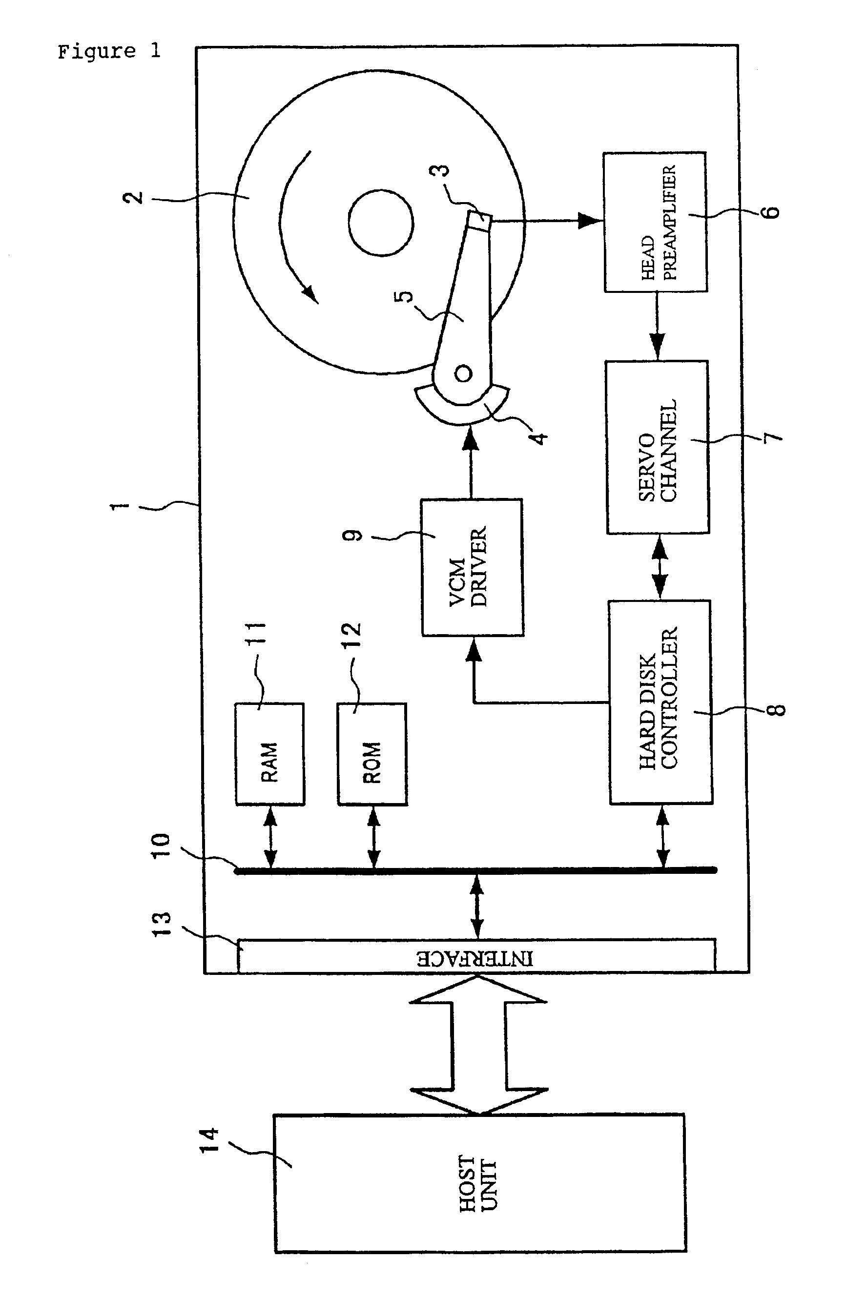
[0018]FIG. 1 is a block diagram of a hard disk drive to be inspected with use of the inspection method in this embodiment. A hard disk drive 1 in this embodiment is configured by a magnetic recording medium 2; a head 3; a voice coil motor (VCM) 4; an arm 5; a head preamplifier 6; a servo channel 7; a hard disk controller 8; a VCM driver 9; a bus 10; a RAM (random access memory) 11; a ROM (read only memory) 12; and an interface 13.

[0019]The magnetic recording medium 2 is a disk-like recording medium on which information is written magnetically. The recording medium 2 is driven rotationally by, for example, a spindl...


PUM

PropertyMeasurementUnit
widthaaaaaaaaaa
surface analysis testaaaaaaaaaa
defect testaaaaaaaaaa

Abstract

In addition to the conventional test pattern writing in a center of each track and inspection of burst patterns (A and B patterns) through a writing test in a SAT, there is also performed a test pattern data writing test, which is done at each boundary between tracks. With this additional test, it is possible to accurately inspect both C and D burst patterns that are sensitive to a PES signal at each boundary between tracks.

Description

BACKGROUND OF THE INVENTION[0001]1. Field of the Invention[0002]The present invention relates to an inspecting method employed for inspecting a surface of a magnetic recording medium of a hard disk drive (hereinafter, to be described as the HDD), more particularly to a technique for improving a detection efficiency of defects in a surface analysis test (SAT).[0003]2. Background of the Invention[0004]Various inspections are carried out for each HDD before delivery. Especially, a surface analysis test (SAT) is carried out as a defect test for the servo information written on a surface of each magnetic recording medium. In a usual SAT, a servo information defect is detected according to a decision of whether or not predetermined test pattern data can be normally written in a center of each track, for example, whether or not the data is normally written by the number of predetermined times. Whether or not the head following to the center of each track (controlling the movement of the he...

Claims


Application Information

Patent Timeline
Patent Type & Authority Patents(United States)
IPC IPC(8): G11B27/36G11B20/18G11B19/04G11B33/00G11B33/10G11B21/10
CPCG11B19/04G11B20/1816G11B20/182G11B27/36G11B33/10
Inventor HATTORI, RYOHEITAKAGAMI, NAOYUKIKOKUBO, TETESUYAMATSUBARA, NOBUYAUMEMURA, KAORU
Owner HITACHI GLOBAL STORAGE TECH NETHERLANDS BV
Why Eureka
Try Eureka