Adaptive rate shaping to prevent overflow

a technology of adaptive rate and overflow, applied in data switching networks, instruments, frequency-division multiplexes, etc., can solve the problems of buffers not being able to prevent overflow, complex and expensive synchronization per bit, and cannot be used on all data networks, so as to eliminate the need for expensive and complex clock synchronization

Inactive Publication Date: 2005-08-30
CISCO TECH INC
View PDF1 Cites 51 Cited by
  • Summary
  • Abstract
  • Description
  • Claims
  • Application Information

AI Technical Summary

Benefits of technology

[0008]The present invention eliminates the need for expensive and complex clock synchronization required in existing synchronous computer networks, such as the Synchronous Optical NETwork (“SONET”) network.

Problems solved by technology

A major problem in a synchronous data network is preventing data overflow in a node in which data is being received faster than it is being transmitted.
This method requires synchronizing on a per bit basis which is complex and expensive and can not be used on all data networks.
The disadvantages of this method are that the buffer adds delay to the transfer of data through the node, the addition of a buffer to the node increases the cost of the node and the buffer cannot prevent overflow if the buffer is not large enough.
Flow control requires large buffers which add delay through the node.
Also, flow control can not be used in all data networks, such as wide area networks.

Method used


Image

  • Adaptive rate shaping to prevent overflow
  • Adaptive rate shaping to prevent overflow
  • Adaptive rate shaping to prevent overflow

Examples


Embodiment Construction

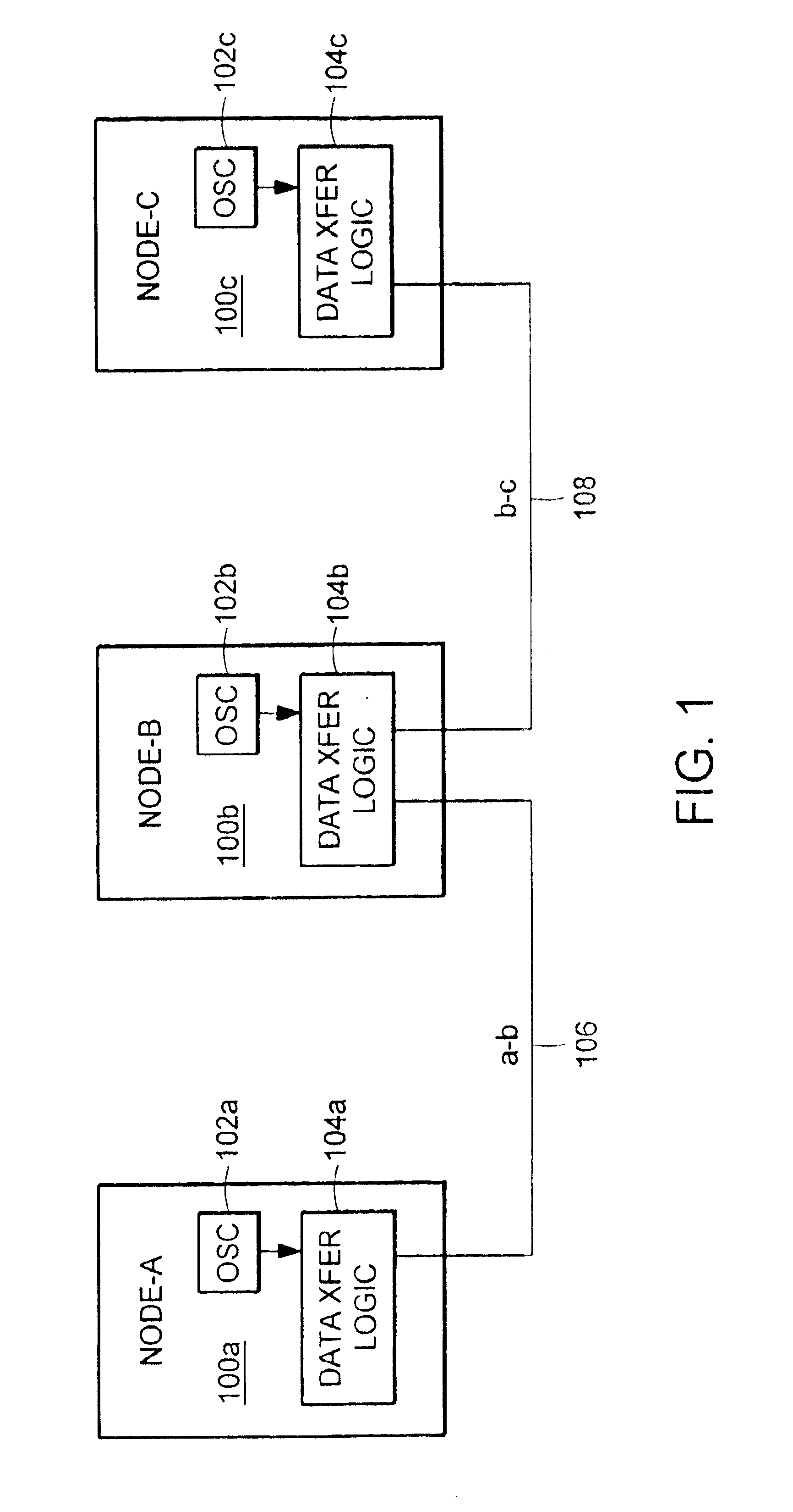
[0016]FIG. 1 illustrates a computer network with three nodes 100a-c connected through computer links 106, 108. Each of the nodes includes an oscillator 102a-c and data transfer logic 104a-c. The nodes 100a-c connected to the network operate in “free-run” mode. That is, the receive clock is derived from the incoming receive data stream and the transmit clock is derived from the local oscillators 102a-c. The receive clock is encoded in the incoming receive data stream using techniques well known in the art, for example, Manchester encoding or 8B / 10B encoding.

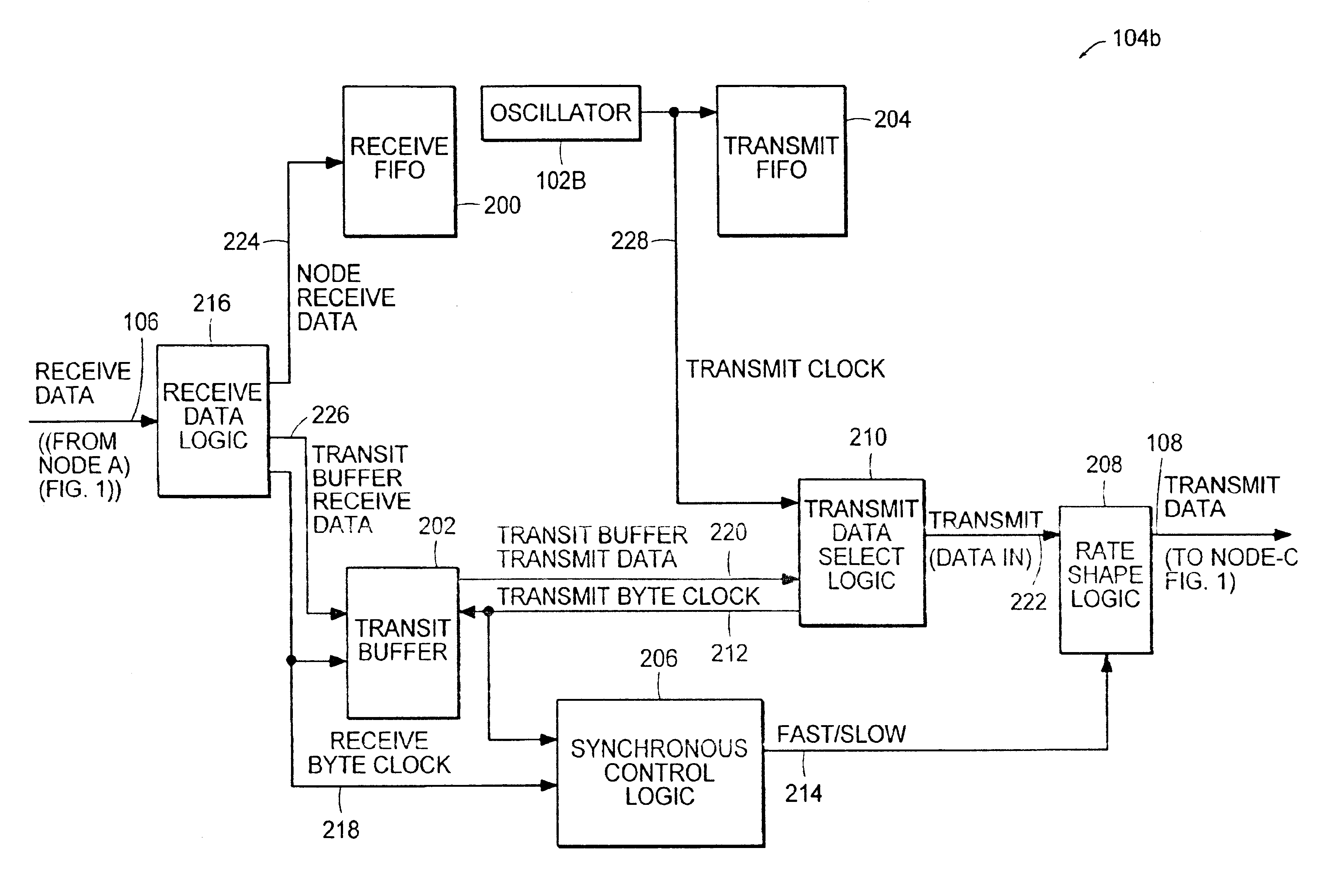
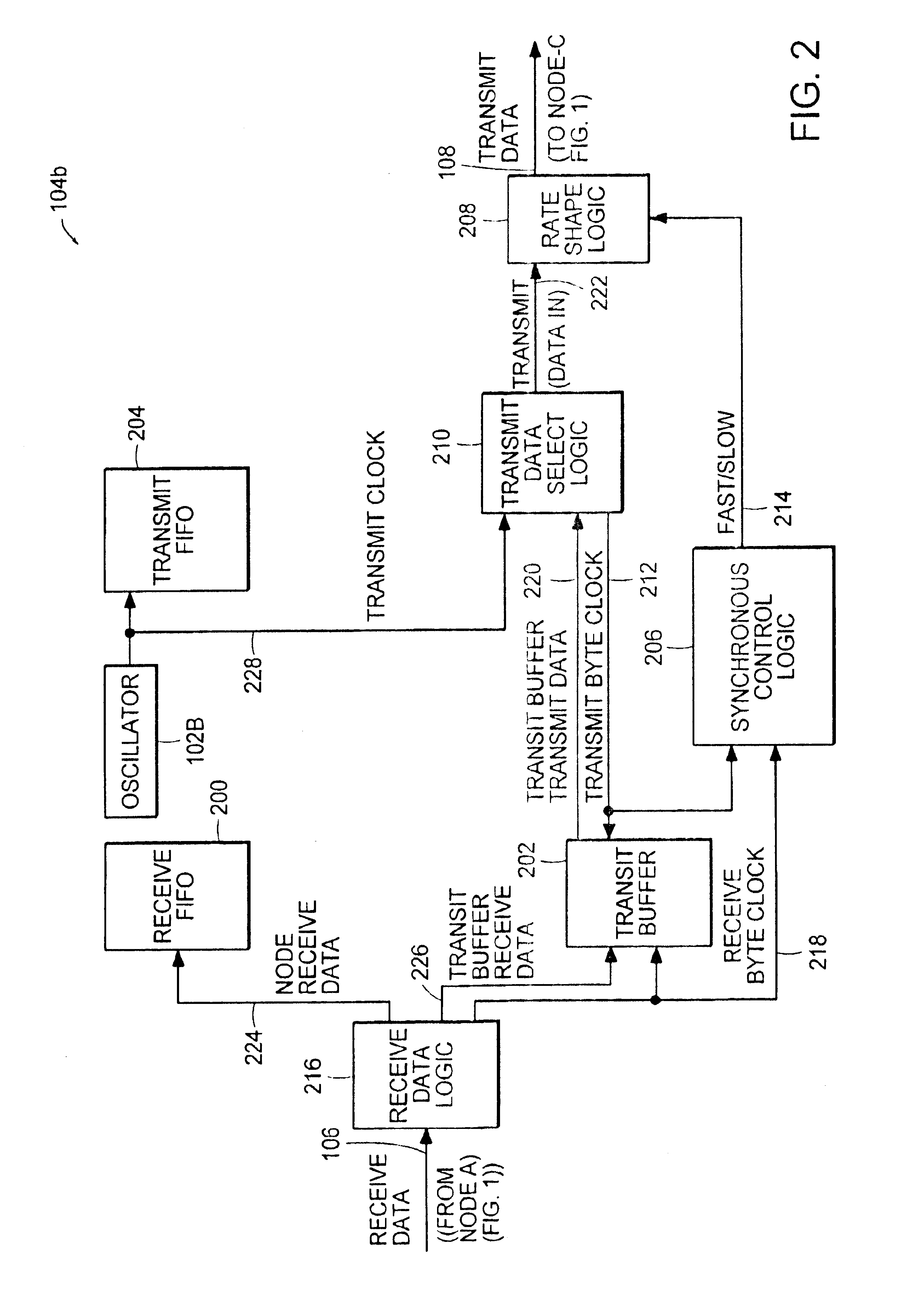
[0017]Node_A 100a is connected to Node_B 110b through communications link a-b 106. Node_B 100b is connected to Node_C 100c through communications link b-c 108. In order to transmit data from Node_A 100a to Node_C 100c, the data flows through the data transfer logic 104b in Node_B 100b. The rate at which data is transmitted from Node_A 100a is dependent on the frequency of Node_A's oscillator 102a. The rate at which data is transmi...


PUM


Abstract

The rate at which a node transmits data is modified dependent on the receive rate by selecting one of a plurality of predetermined quantum values dependent on the difference between the number of bytes received and the number of bytes transmitted. An offset equal to the difference between the number of bytes transmitted and the number of bytes received is compared to a predetermined threshold value. A predetermined quantum value is selected dependent on the result of the comparison. Rate shaping is applied to the transmit data by halting data transmission for an inter-gap interval dependent on the selected quantum value.

Description

BACKGROUND OF THE INVENTION[0001]A major problem in a synchronous data network is preventing data overflow in a node in which data is being received faster than it is being transmitted. Receive and transmit data rates in a node differ if there is a difference in frequency between the receive clock and the transmit clock. This frequency difference occurs if the transmit data rate is dependent on the node's transmit clock and the receive data rate is dependent on the adjacent node's transmit clock.[0002]One method for preventing overflow is to synchronize the transmit clock and the receive clock. One such clock synchronization method is described in U.S. Pat. No. 5,896,427 issued on Apr. 20, 1999 entitled “System and Method for Maintaining Network Synchronization Utilizing Digital Phase Comparison Techniques with Synchronous Residual Time Stamps” by Muntz et al. This method requires synchronizing on a per bit basis which is complex and expensive and can not be used on all data network...

Claims


Application Information

Patent Timeline
Patent Type & Authority Patents(United States)
IPC IPC(8): H04J1/16H04J1/00H04J3/06
CPCH04J3/0632
Inventor NICHOLL, GARYOUELLET, JEAN-YVESTSIANG, DAVID
Owner CISCO TECH INC
Why Eureka
Try Eureka