Skew correction apparatus

Inactive Publication Date: 2005-08-30
FUJITSU LTD
View PDF2 Cites 71 Cited by
  • Summary
  • Abstract
  • Description
  • Claims
  • Application Information

AI Technical Summary

Benefits of technology

[0024]In a high-speed transmission system, the code conversion is usually employed (for example, 4B5B conversion or 8B10B conversion) to improve the transmission quality. Therefore, the imbalance of the code duty of th

Problems solved by technology

As a result, the problem is posed that the increase in data transmission rate and the number of bytes are restrained.
From the viewpoint of the data transmission quality of the computer system, however, it is not des

Method used


Image

  • Skew correction apparatus
  • Skew correction apparatus
  • Skew correction apparatus

Examples


Example

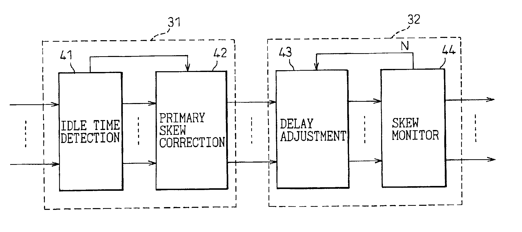
[0039]An embodiment of the invention will be described in detail below with reference to the drawings.

[0040]FIG. 3 is a block diagram schematically showing a skew correction circuit according to the invention. This skew correction circuit is incorporated in a receiver for receiving a plurality of serial data through a plurality of channels and reducing the skew amount constituting a phase shift between the plural serial data. In FIG. 3, each of the data DATA0 to DATAn (hereinafter referred to as the data 0 to n) is serial data. Primary skew correction means 31 detects the skew amount between the plural serial data 0 to n in idle state when no data is transmitted, and corrects each delay amount of the serial data in such a manner as to reduce the skew amount to zero. Secondary skew correction means 32 detects the skew amount generated between a plurality of serial data during the data transmission, based on the state corrected by the primary skew correction means 31, and corrects the...


PUM


Abstract

A skew correction apparatus for increasing the data transfer capacity and thus improving the system performance, by making it possible to carry out the deskew work even during the data transfer, is disclosed. The skew correction apparatus receives a plurality of serial data in synchronism, and reduces the skew mount constituting a phase shift between the serial data. A first correction unit (31) detects a skew between the serial data and corrects the skew during the idle time. A second skew correction unit (32) detects a skew between the serial data and corrects the skew during the data transmission.

Description

BACKGROUND OF THE INVENTION[0001]1. Field of the Invention[0002]The present invention relates to a skew correction apparatus or, in particular, to a skew correction apparatus for reducing the skew amount constituting a phase shift at the receiving end of a data transmission system.[0003]2. Description of the Related Art[0004]FIG. 1 is a block diagram showing the most basic parallel data transmission system according to the prior art. In FIG. 1, data DATA0 to DATA3 and a byte clock signal CLK are transmitted in parallel through a plurality of transmission channels 12-1 to 12-5 between a transmitter 10 and a receiver 11. The DATA0 to DATA3 are each an 8-bit serial data. In the case where variations occur in the device characteristics or the cable transmission delay time between the transmission channels 12-1 to 12-5, the skew constituting a phase shift occurs between transmission channels. As a result, the problem is posed that the increase in data transmission rate and the number of ...

Claims


Application Information

Patent Timeline
IPC IPC(8): H04L25/14G06F13/42G06F1/12H03K5/00H03K5/13H04L7/00H04L25/02H04L25/40
CPCH04L25/14
Inventor WATANABE, TAKAYUKI
Owner FUJITSU LTD
Why Eureka
Try Eureka